Set the control throws, Balance the model (c.g.) – Great Planes P-51 Mustang GP/EP ARF - GPMA1205 User Manual
Page 20
20
Set the Control Throws
Use a Great Planes AccuThrow (or a ruler) to accurately
measure and set the control throw of each control surface
as indicated in the chart that follows. If your radio does not
have dual rates, we recommend setting the throws at the
low
rate setting.
NOTE
: The throws are measured at the
widest part
of the
elevators, rudder and ailerons.
These are the recommended control surface throws:
ELEV
A
T
OR
R
UDDER
AILER
ONS
LOW RATE
5/16"
[8mm]
9°
Up & Down
1/4"
[6mm]
9°
Up & Down
1-7/16"
[37mm]
27°
Right & Left
HIGH RATE
7/16"
[11mm]
12°
Up & Down
5/16"
[8mm]
11°
Up & Down
1-7/8"
[48mm]
36°
Right & Left
IMPORTANT:
The Sport Scale P-51 ARF has been
extensively
fl own and tested to arrive at the throws at
which it fl ies best. Flying your model at these throws will
provide you with the greatest chance for successful fi rst
fl ights. If, after you have become accustomed to the way
the P-51 fl ies, you would like to change the throws to suit
your taste, that is fi ne. However, too much control throw
could make the model diffi cult to control, so remember,
“more is not always better.”
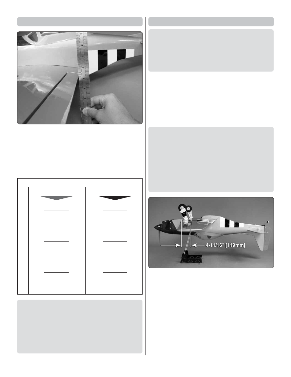
Balance the Model (C.G.)
More than any other factor, the
C.G.
(balance point) can
have the
greatest
effect on how a model fl ies, and may
determine whether or not your fi rst fl ight will be successful.
If you value this model and wish to enjoy it for many fl ights,
DO NOT OVERLOOK THIS IMPORTANT PROCEDURE.
A model that is not properly balanced will be unstable and
possibly unfl yable.
At this stage the model should be in ready-to-fl y condition with
all of the systems in place including the engine or brushless
motor, landing gear, and the radio system (and battery pack
if applicable).
❏
1. Use a felt-tip pen or 1/8" [3mm]-wide tape to accurately
mark the C.G. on the bottom of the wing on both sides of the
fuselage. The C.G. is located 4-11/16" [119mm] back from
the leading edge of the wing.
This is where your model should balance for the fi rst fl ights.
Later, you may wish to experiment by shifting the C.G. up
to 1/4" [6mm] forward or 7/16" [11mm] back to change the
fl ying characteristics. Moving the C.G. forward may improve
the smoothness and stability, but the model may then
require more speed for takeoff and make it more diffi cult
to slow for landing. Moving the C.G. aft makes the model
more maneuverable, but could also cause it to become too
diffi cult to control. In any case,
start at the recommended
balance point
and do not at any time balance the model
outside the specifi ed range.
❏
2. With the wing attached to the fuselage, all parts of the
model installed (ready to fl y) and an empty fuel tank, place the
model on a Great Planes CG Machine, or lift it upside-down
at the balance point you marked.
❏
3. If the tail drops, the model is “tail heavy” and the battery
pack and/or receiver must be shifted forward or weight must
be added to the nose to balance. If the nose drops, the model
is “nose heavy” and the battery pack and/or receiver must be
shifted aft or weight must be added to the tail to balance. If
possible, relocate the battery pack and receiver to minimize or
eliminate any additional ballast required. If additional weight is
required, nose weight may be easily added by using a “spinner
weight” (GPMQ4645 for the 1 oz. [28g] weight, or GPMQ4646