Check the control directions center the servos – Great Planes Giant Big Stik ARF - GPMA1224 User Manual
Page 21
❏
4. Take the tray out of the fuselage, then use the included
Velcro strips and R/C foam rubber (not included) to mount the
receiver and battery. Add a few drops of thin CA to the screw
holes, allow the glue to harden, then mount the tray back into
the fuselage.
❏
5. Mount the receiver on/off switch in a location that is
easily accessible and will not get coated by engine exhaust.
A Great Planes Switch & Charge Jack Mounting Set
(GPMM1000) was used on this model and is a great way to
easily connect to the battery pack for voltage monitoring.
❏
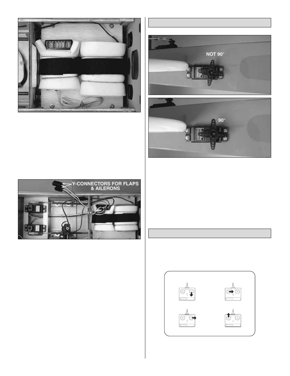
6. Connect the servos in the fuselage to the receiver.
Guide the receiver antenna away from the servos and on/off
switch and down through the antenna tube that is factory-
built into the fuselage. Note the Y-connectors connected to
the receiver for the flaps and ailerons.
With the radio system connected and operating, turn on the
transmitter and receiver. Make sure the trims on the
transmitter are centered. Starting with the rudder servo, test
fit the four-arm servo arm in one of the four positions until
you find the one that is 90-degrees. Cut off the remaining
arms. Repeat this procedure for the rest of the servos. Note:
For this procedure, the flap servos cannot be connected to
a function operated by a two-position switch. Temporarily
connect the flap servos to a function that has a center (such
as one of the control sticks or a slider) to find the servo arm
that will be 90-degrees.
❏
1. With the transmitter and receiver still on, check all the
control surfaces to see if they are centered. If necessary, adjust
the clevises on the pushrods to center the control surfaces.
❏
2. Make certain that the control surfaces and the carburetor
respond in the correct direction as shown in the diagram. If
any of the controls respond in the wrong direction, use the
CARBURETOR WIDE OPEN
RUDDER MOVES RIGHT
LEFT AILERON MOVES DOWN
RIGHT AILERON MOVES UP
ELEVATOR MOVES UP
4-CHANNEL
TRANSMITTER
(STANDARD MODE 2)
4-CHANNEL RADIO SETUP
TRANSMITTER
4-CHANNEL
TRANSMITTER
4-CHANNEL
TRANSMITTER
4-CHANNEL
Check the Control Directions
Center the Servos
21