Mount the engine – Great Planes Giant Big Stik ARF - GPMA1224 User Manual
Page 16
GLOW ENGINE
❏
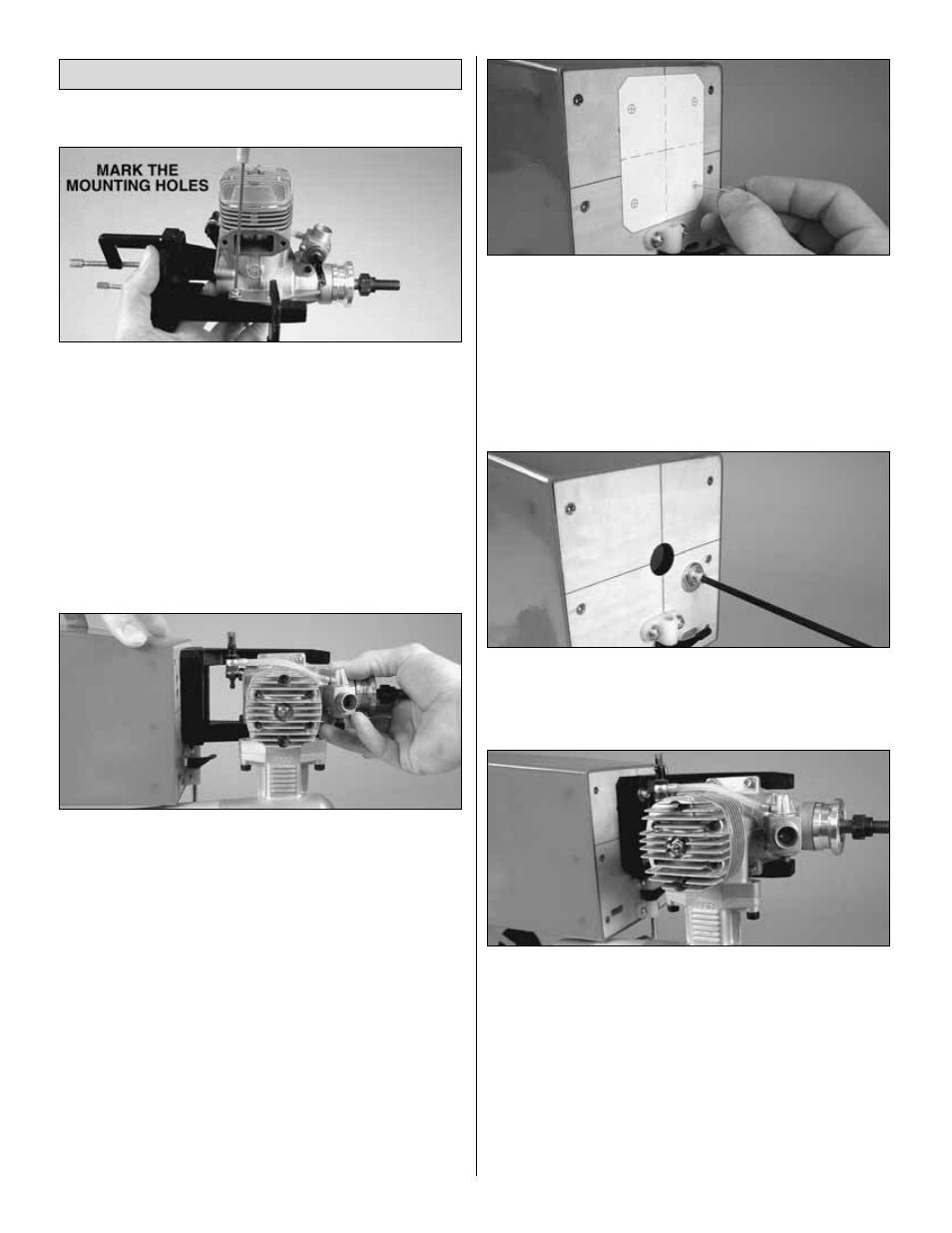
1. Fit the engine to the engine mount halves and hold the
assembly together using small C-clamps. (Since this plane
has no engine cowl it doesn’t matter how far forward or aft
you position the engine on the mount.) Use a Great Planes
Engine Hole Locator or a drill bit to mark the engine
mounting holes into the engine mounts.
❏
2. Take the engine off the mount. Drill #29 holes at the
marks. Use an 8-32 tap to cut threads into the holes. Mount
the engine to the mount with four 8-32 x 1" [25mm] socket
head cap screws and #8 lock washers.
❏
3. Temporarily mount the muffler to your engine. Hold the
engine and mount to the firewall to see which way it will be
mounted. As shown in the photo, side mounting is preferred
as the engine exhaust will be under the fuselage. But in
order to side mount the engine, the muffler must clear the
nose gear and the bottom of the fuselage. If it does not, you
will have to mount the engine a different way. Note: The
engine must be centered laterally on the vertical line on the
firewall, but it is okay to move the engine up, above the
horizontal line in order to clear the nose gear bearing.
❏
4. Once you have decided which way to mount the
engine, cut out the Glow Engine Mounting Template from
the back of the manual. As the supplied Great Planes
engine mount is adjustable and the mounting bolt holes are
slotted, the crossmarks for the bolt holes on the template
will work for all engines that fit the mount, but the outline
depicts the engine mount “footprint” when an O.S. 1.60 FX
is mounted.
❏
5. Use tape or spray adhesive to hold the glow engine
mount template to the firewall. As mentioned before, the
vertical line on the template should align with the vertical
line on the firewall, but it is okay if you have to raise the
template so the mount will clear the nose gear bearing. If
the nose gear is not in the way, center the horizontal line on
the template with the horizontal line on the firewall as well.
Use a large T-pin or a wire sharpened on the end to transfer
the bolt hole marks on the template into the firewall.
❏
6. Drill 13/64" [5.2mm] (or 3/16" [4.8mm]) holes at the
marks. Apply a few dabs of epoxy to the front of four 8-32
blind nuts. Use an 8-32 x 1-1/4" [32mm] bolt with large
washers to draw the blind nuts into the back of the firewall.
❏
7. Mount the engine mount with the engine to the firewall
using four 8-32 x 1-1/4" [32mm] socket head cap screws
and #8 flat washers and lock washers.
GAS ENGINE (FUJI BT-32)
If mounting a gas engine other than the Fuji BT-32, use
these instructions for ideas how to mount your engine in a
similar manner.
Mount the Engine
16