Apply the decals, Set the control throws – Great Planes Extra 300SP EP ARF - GPMA1188 User Manual
Page 17
17
❏
3. Install the spinner back plate onto the motor shaft. Enlarge
the hole in the back plate as needed to fi t your brand of motor.
Remove the spinner back plate. Do not complete the installation
of the prop and spinner until the entire radio system has been
set up. This will prevent the possibility of any mishaps prior to
preparing the model for fl ight.
Apply the Decals
The box photographs show the location of the decals on the
airplane. Refer to these for the exact placement of the decals.
The following tips may be useful for applying them.
❏
1. Be certain the model is clean and free from oily fi ngerprints
and dust. Prepare a dishpan or small bucket with a mixture
of liquid dish soap and warm water—about one teaspoon of
soap per gallon of water. Submerse the decal in the soap and
water and peel off the paper backing. Note: Even though the
decals have a “sticky-back” and are not the water transfer type,
submersing them in soap & water allows accurate positioning
and reduces air bubbles underneath.
❏
2. Position decals on the model. Holding the decal down,
use a paper towel to wipe most of the water away.
❏
3. Use a piece of soft balsa or something similar to squeegee
remaining water from under the decal. Apply the rest of the
decals the same way.
GET THE MODEL READY TO FLY
Check the Control Directions
❏
1. Turn on the transmitter and receiver and center the trims.
If necessary, remove the servo arms from the servos and
reposition them so they are centered. Reinstall the screws
that hold on the servo arms.
❏
2. With the transmitter and receiver still on, check all the
control surfaces to see if they are centered. If necessary, adjust
the clevises on the pushrods to center the control surfaces.
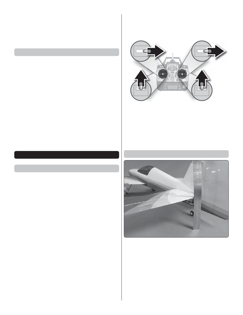
FULL
THROTTLE
RUDDER
MOVES
RIGHT
ELEVATOR
MOVES DOWN
RIGHT AILERON
MOVES UP
LEFT AILERON
MOVES DOWN
4-CHANNEL RADIO SET UP
(STANDARD MODE 2)
❏
3. Make certain that the control surfaces and the throttle
respond in the correct direction as shown in the diagram. If any
of the controls respond in the wrong direction, use the servo
reversing in the transmitter to reverse the servos connected to
those controls. Be certain the control surfaces have remained
centered. Adjust if necessary.
Set the Control Throws
Use a ruler to accurately measure and set the control throw
of each control surface as indicated in the chart that follows.
If your radio does not have dual rates, we recommend setting
the throws at the low rate setting.
NOTE: The throws are measured at the widest part of the
elevators, rudder and ailerons.