Great Planes Dirty Birdy .60 ARF - GPMA1975 User Manual
Page 34
30
❏
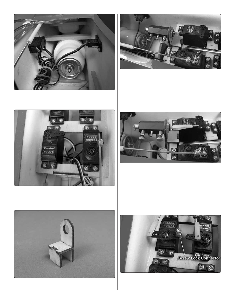
6. Insert the air tank into the nose of the fuselage, pushing
it as far forward as it will go. Cut a piece of scrap balsa to
secure the tank in place as shown.
❏
7. Install your retract valve servo in the location shown.
Cut three arms from a four-armed servo arm and install it
perpendicular to the servo case. Enlarge the outer hole of
the remaining arm with a 5/64" [2mm] drill bit.
❏
8. Assemble the plywood air valve mount.
❏
9. Insert the threaded end of the air valve through the hole
in the mount. Apply a few drops of thread locking compound
and tighten the valve against the mount using the knurled nut.
Rotate the valve so the adjustment needles will be on their
side when installed in the fuselage. This will prevent them from
interfering with the wing. Use a pair of pliers to snug down the
knurled nut. Use thick CA or epoxy to glue the valve mount to
the servo tray in the location shown.
❏
10. Make an actuator pushrod from the included 12"
[305mm] pushrod by cutting off approximately half of the
threads at one end and make a Z-bend at the other. Thread a
nylon clevis onto the threaded end of the pushrod and attach
the clevis to the valve.
CAUTION:
You will need to reduce the
travel of your actuator servo to approximately 20% of full travel
in each direction. Test the operation of the servo using your
radio system before connecting it to the pushrod. Excessive
travel of the actuator servo when connected to the valve may
break the valve mount.
❏
11. Install a screw lock connector into the outer hole of
the remaining rudder servo arm. Loosely thread a 4-40 x 1/8"
[3mm] SHCS into the screw lock connector.