Great Planes Dirty Birdy .60 ARF - GPMA1975 User Manual
Page 19
19
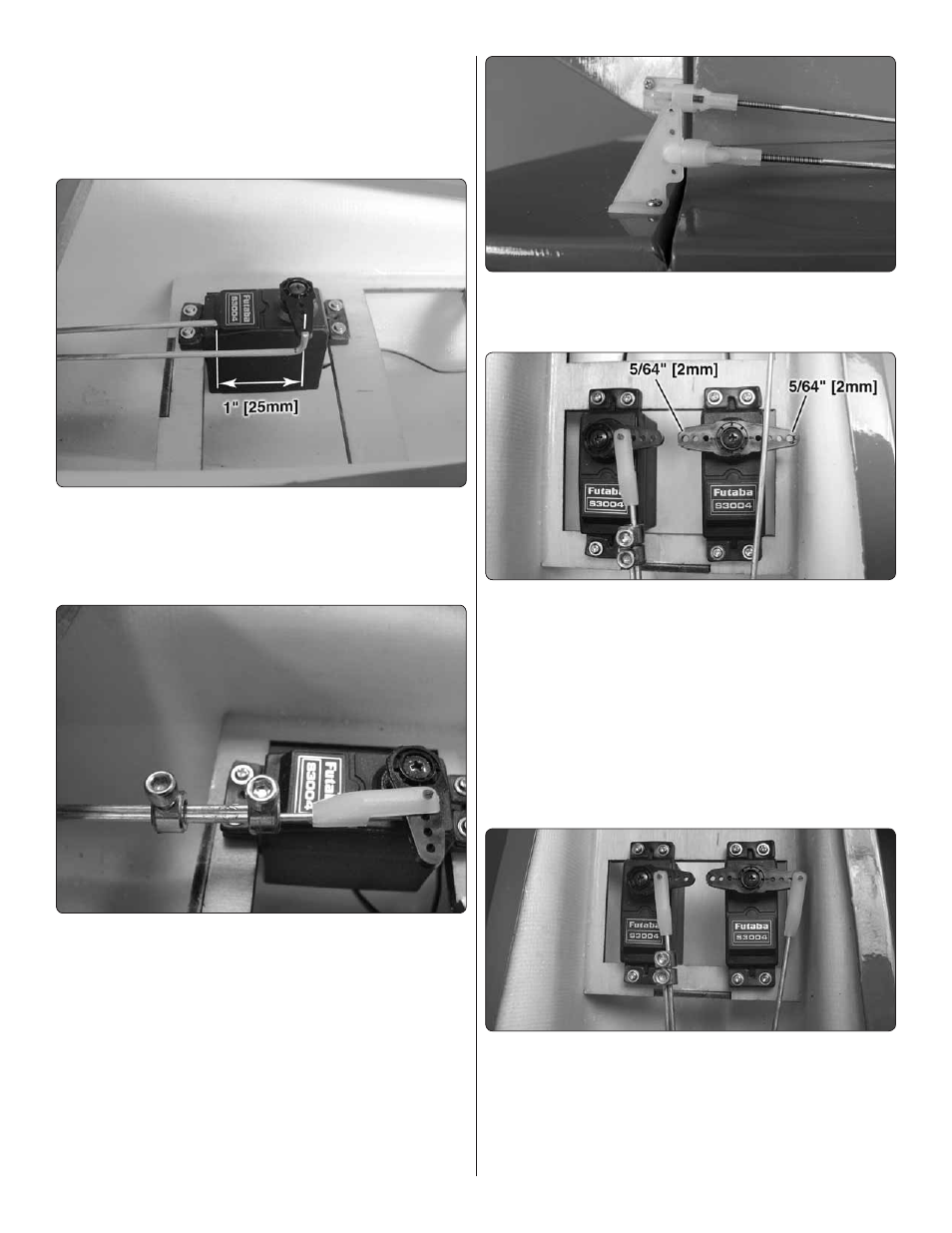
arms to match the photo. Enlarge the inner hole on the arm
with a 5/64" [2mm] drill bit. Using the mounting hardware
included with the servo, install it so there is approximately
3/8" [9.5mm] gap between the servo and the inner edge of
the tray. Be sure to harden the servo mounting holes with thin
CA glue.
❏
7. Center the right elevator and make a bend in the pushrod
where it crosses the inner hole of the elevator servo arm.
Center the left elevator and make a mark on the pushrod
1" [25mm] aft of the inner hole of the servo arm. Cut off the
excess pushrod at your mark.
❏
8. Loosely thread a 6-32 x 1/4" [6.4mm] SHCS into two
5/32" [4mm] wheel collars with threadlocking compound. Fit
the wheel collars over both pushrod ends. Connect the right
elevator pushrod to the servo arm and secure it with a FasLink.
Slide both wheel collars just to the end of the left elevator
pushrod, view the plane from behind and confi rm that both
elevator halves are parallel, and
thoroughly
tighten the screws
in the wheel collars. Test the operation of the elevator servo
with your radio. Make any fi ne adjustments with the clevises
to bring the elevator halves perfectly parallel with each other.
❏
9. Install the rudder control horn using the remaining 2-56
x 36" [914mm] pushrod. The clevis should be connected to
the second
inner
hole of the control horn.
Read all of step 10 before proceeding.
❏
10. Electronically center your rudder servo and choose the
best orientation of the four-armed servo arm. Cut off the two
unused arms as shown in the picture. The remaining
right
servo arm was trimmed down to three holes (note that the
photo shows the plane upside down). Enlarge the outer holes
of both remaining arms with a 5/64" [2mm] drill bit.
IF
you will
be using the
fi xed
nose gear, the right servo arm described
in this step is not necessary and can be cut off. The steering
pushrod used for the fi xed gear requires you to enlarge the
second inner hole of the only remaining servo arm. Install
the servo as shown.
❏
11. Center the rudder and mark where the rudder pushrod
crosses the outer hole of the
left
servo arm and make a mark
at that location. Bend the pushrod 90 degrees at your mark,
cut off the pushrod 1/4" [6mm] beyond your mark and connect
the pushrod to the servo arm with a FasLink. Adjust the clevis
accordingly so the rudder is neutral when the servo arm is
perpendicular to the servo case.