Gpmz0026e – Great Planes Ammo 36mm Power System - GPMG5240-5325 User Manual
Page 5
Once the pinion gear is in position on the motor shaft, apply
a drop of Great Planes Threadlocker (GPMR6060) to the
threads of the set screw and tighten it down on the flat of
the motor shaft.
REMOVAL OF THE PINION GEAR
The best method of removing the pinion gear is by heating
it with a micro torch and using a pinion puller to carefully
pull the gear off.
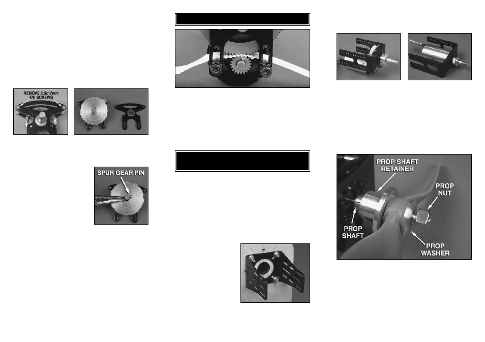
REPLACING THE SPUR GEAR
To remove the spur gear, loosen and remove the two
2.5x17mm flat head machine screws and 5.5mm aluminum
spacers.Remove the backplate, being careful to not lose
the 6mm bearing spacer.
Press the output shaft out of the
spur gear and remove the spur
gear pin. The spur gear can now
be replaced. Reverse the order to
reassemble the gear drive. Be
sure to use a drop of threadlocker
on the two 2.5x17mm flat head
machine screws to prevent them
from loosening during operation.
70/14 =
5:1
70/20 = 3.5:1
90/14 = 6.42:1
90/20 = 4.5:1
MOUNT THE MOTOR TO THE GEAR DRIVE
Loosely mount the motor to the back of the back plate with
two 3x23mm SHC screws and two 3mm flat washers. Place
a piece of notebook paper between the pinion gear and the
spur gear. Squeeze the two gears together while tightening
the two 3x23mm SHC screws. Remove the piece of paper
and the gear mesh should be set. Rotate the gears to make
sure they rotate smoothly. If they do not, slightly loosen the
SHC screws and adjust the gear mesh until the gears do
rotate smoothly.
MOUNT THE BRUSHLESS
LARGE MOTOR MOUNT
In the center of the header card you will find the mounting
hole pattern template for the Brushless Large Motor Mount.
The Motor Mount has the same bolt mounting pattern as
the Great Planes .40-.70 and .60-1.20 Nylon Engine
Mounts. If you are replacing a glow engine with an electric
motor system, remove the nylon engine mount and replace
it with the Large Motor Mount using the same bolts to
attach it to the firewall. If the firewall has not been drilled for
an engine mount and blind nuts, use the mounting template
on the header card to locate the mounting holes.
Attach the Backplate to the
firewall using four 6-32
machine screws and four
#6 flat washers when
replacing the .40-.70 nylon
mount; or four 8-32
machine screws and four
#8 flat washers when
replacing the .60-1.20
nylon mount. Note that if
you are using a gear drive
you may have to cut a hole in the firewall for the motor. The
motor and gear drive can be mounted to the Front Plate
using the 3x8mm machine screws. If you are using a gear
drive other than the Great Planes gear drive, the hole
locations may need to be modified. Also, if you are mounting
the motor to a firewall, longer screws may be required.
In-runner motors that will be run direct drive or gear drive
and are mounted inside the front plate.
Install the prop adapter on the motor shaft or gear drive
output shaft. The Brushless 36mm Gear Drive uses a 6mm
prop adapter (GPMQ4968 Collet Type or GPMQ4942 Set
Screw Type). The Ammo 36mm motors direct drive uses the
5mm prop adapter (GPMQ4966 Collet Type or GPMQ4939
Set Screw Type).
COLLET TYPE PROP ADAPTER INSTALLATION
Slide the prop shaft over the output shaft of the gear drive or
motor. Next slide the prop shaft retainer over the prop shaft.
Note that the hole through the retainer is tapered. Make sure
that the side with the larger diameter hole is installed first.
Install the spinner backplate (if used, not included), the
prop, prop washer and then the prop nut. Tighten the prop
nut against the prop. This will cause the tapered hole in the
prop shaft retainer to squeeze the prop shaft around the
output shaft. Carefully pull on the prop to make sure it is
securely attached to the output shaft of the gear drive.