Automatic transmitter frequency setting (asc), Trc receiver setup: transmitter status indications – Galaxy Audio TRC User Manual
Page 8
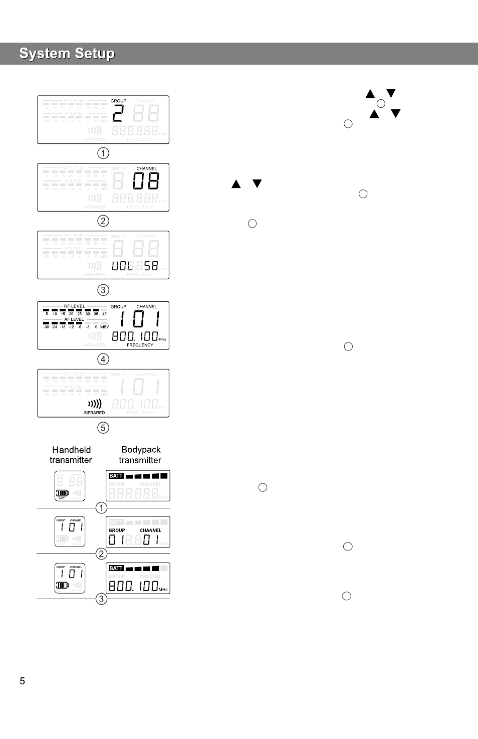
Frequency Group No. and Channel No. selection:
Press“SET
”
key, and “GROUP
”
will flash. Press
or
key to select
suitable frequency group number, as shown in Diagram
on the left. Then
1
press“SET
”
key, and “CHANNEL
”
flashes. Press
or
key to
select suitable channel, as shown in Diagram
on the left.
2
Note: when using several systems, you may set all the systems
to the same group number, and then set a unique channel for each system
in this group.
Receiver Volume Control:
This device features an electronic volume control system. Under the normal
screen, press
or
key to control the output volume of the receiver
(there are 64 volume levels) as shown in Diagram
on the left.
3
Normal Display:
RF level, Audio Level, Group Number, Channel, and Frequency, as
shown in Diagram
on the left.
4
Automatic Transmitter Frequency Setting (ASC):
Point its IR window towards the IR window on the Receiver. Press the
“ASC
”
key on the Receiver. Verify the frequencies match.
Point the IR window of the Bodypack Transmitter towards the IR window of the
Receiver. Press “ASC
”
key on the Receiver and then the “ASC
”
key of
the Bodypack Transmitter.
Whenever the “ASC
”
key of the receiver is pressed, synchronizing signal
will be transmitted continuously for 25 sec, and “INFRARED
”
symbol on
the screen also flashes, as shown in Diagram
on the left.
5
When the infrared receiving circuit is enabled, “INFRARED
”
symbol on
the Handheld Transmitter will flash and the entire display screen of the
Bodypack Transmitter will flash (the infrared transmission indicator lamp will
also flash at the same time).
Notes: when establishing infrared connection between the receiver and the
transmitter, the distance between them should not exceed 0.5m. When more
than one system are used, only IR window of one transmitter should be pointed
to the receiver for each infrared connection.
Battery voltage indication:
There are five battery voltage level indicators for the Handheld Transmitter,
and there are six battery voltage level indicators for waist worn transmitter,
as shown in Diagram
on the left.
1
Group Number and Channel Number Indication:
After the infrared connection between the receiver and the transmitter is
completed, the same group number and channel as those of the receiver
will be indicated on the Handheld transmitter, and the display screen of
the Bodypack Transmitter will give a 5-sec steady indication of the Group
and Channel Numbers, as shown in Diagram
on the left. Then it returns
to normal status indications.
Normal Indications on the Display:
Battery voltage, group number and channel are displayed on the Handheld
Transmitter, and battery voltage and frequency are displayed on the
Bodypack Transmitter, as shown in Diagram
on the left.
2
3
TRC Receiver Setup:
Transmitter Status Indications:
HH64 Handheld Transmitter:
MBP64 Bodypack Transmitter:
Verify the frequencies match.