Galaxy Audio TRC User Manual
Page 5
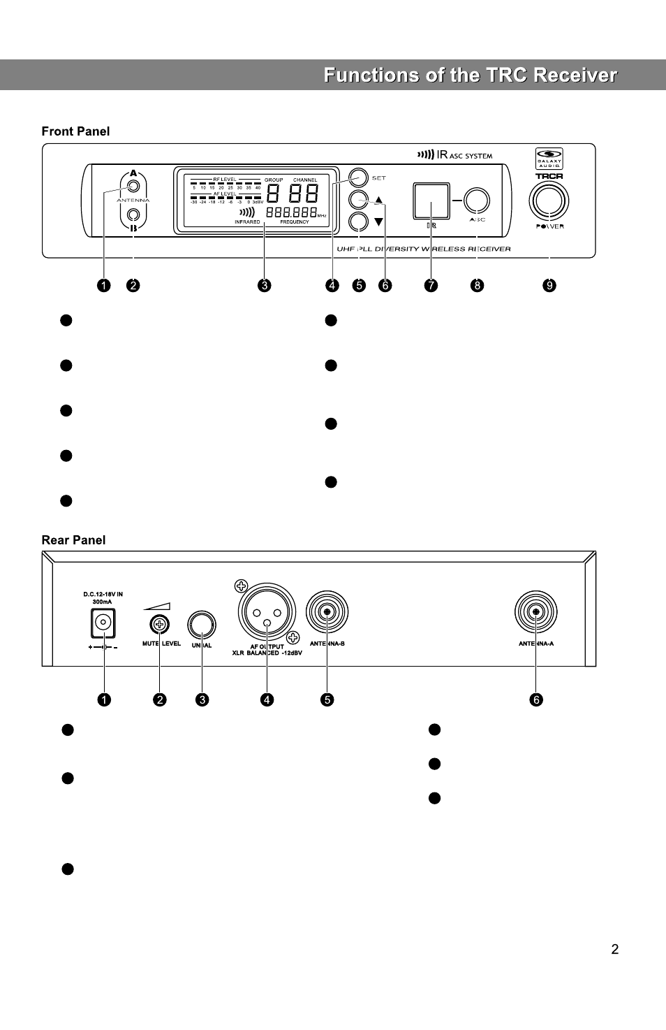
Antenna A LED.
When lit, Antenna A is active.
Antenna B LED.
When lit, Channel B antenna is active.
LCD Panel.
Please See“system setup”on page 7.
System setting button.
Please See“system setup”on page 7.
DOWN button of the System Menu.
Please See“system setup”on page 7.
1
2
3
4
5
Power Adapter Connection. Use only supplied adapter or
equivalent.
Fine adjustment of mute threshold level.
Use this to set the threshold of the mute, which is factory
set and usually does not need to be adjusted. If there are
any interference signals, this threshold value can be increased
by turning the knob clockwise until RF signal lamp goes out.
¼" Audio Output Jack.
1
2
3
UP button of the System Menu.
Please See“system setup”on page 7.
IR window.
This window sends an infrared signal to the transmitter
for frequency synchronization.
Synchronizing signal transmit button
Press this button to establish infrared connection
between the receiver and transmitter.
Power switch
Press and Hold for Power On/Off.
6
7
8
9
XLR Audio Output.
Antenna Jack B 50 ohm.
Antenna Jack A 50 ohm.
4
5
6