Galaxy Audio TRAVELER AS-TV8 User Manual
Page 6
6. Looking inside the bay opening, locate the small switch on the top of the main
circuit board, near the rear edge (See Photo 6). Verify that this switch is in the
position labeled “Effect” (to the left.)
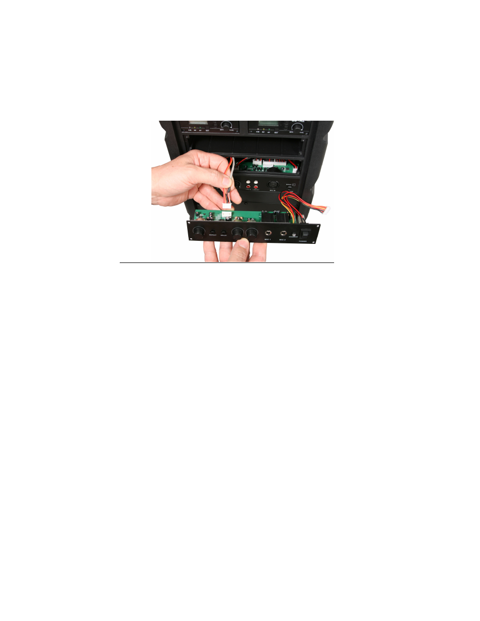
7. Carefully install the TVEC module panel into the bay opening, making sure not to
pinch any wires. Reinstall the four module panel mounting screws.
Photo 9.
See also other documents in the category Galaxy Audio Audio accessories:
- CHECK MATE CM-130 (10 pages)
- CHECK MATE CM-140 (12 pages)
- CHECK MATE CM-150 (24 pages)
- CHECK MATE CM-200 (12 pages)
- CORE 12 (12 pages)
- FAROUTLET 300 S (16 pages)
- CORE X250 (16 pages)
- DS-CP22 (40 pages)
- DS-CP25 (40 pages)
- DS-EQ215 (20 pages)
- DS-EQ230 (40 pages)
- DS-SP24 (40 pages)
- DS-SP36 (40 pages)
- G-440 (16 pages)
- AS-HSA (4 pages)
- ESS (4 pages)
- HSE (2 pages)
- HSD (2 pages)
- HOT SPOT Handle Installation (2 pages)
- HOT SPOT User Guide (24 pages)
- HSVC Hotspot Yoke Bracket (6 pages)
- NSPA (24 pages)
- PA6S BOOM MOUNT KIT (3 pages)
- PA8X140 (12 pages)
- Setting up PA and Monitors (3 pages)
- CRICKET POLARITY TEST SET (14 pages)
- JIB/CT (12 pages)
- JIB/MM (8 pages)
- JIB/PA50 (8 pages)
- JIB/PB (2 pages)
- LA4/LA4PM Yoke Bracket (7 pages)
- LA4/LA4PM (8 pages)
- HDR2 (14 pages)
- RM-CDU (12 pages)
- GA64 / GA64SC (2 pages)
- RM2 (24 pages)
- RM-CD (5 pages)
- RM-CDV (7 pages)
- RM10 (12 pages)
- CK-HH (24 pages)
- TRAVELER AS-TV8 (36 pages)
- AS-M500 (22 pages)
- AS-QUAD (24 pages)
- CTS (20 pages)