Galaxy Audio TRAVELER AS-TV8 User Manual
Page 5
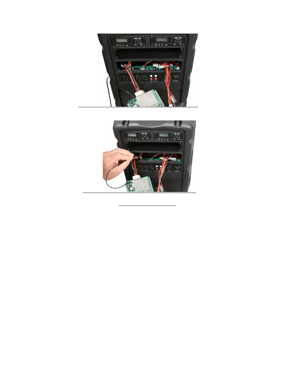
Photo 7.
Photo 8.
AS-TVEC Echo Module:
1. Remove the four panel mounting screws using a Phillips screwdriver. Remove the
existing panel from the bay opening as far as the attached wires will allow.
2. Look inside the bay opening and note the location of the 7-pin connector that
connects the wires from the main power switch to the main circuit board (See
Photo 5). Carefully remove this plug from the circuit board connector. Set aside
the disconnected panel.
3. Looking inside the bay opening, locate the 5-pin connector and wires emerging
from the left side of the main circuit board (See Photo 6). Leave the connector
attached at the circuit board but pull the free end of this wire group out of the bay
opening.
4. Plug this 5-pin connector into the connector located on the top of the TVEC
module circuit board (See Photo 9). Make sure the plug is installed all the way
until the tabs lock.
5. Locate the wires and 7-pin connector emerging from the main power switch on
the TVEC module. Plug this connector into the same 7-pin main circuit board
connector that was previously connected to the main power switch wires on the
removed panel (See Photo 6).