Galaxy Audio TRAVELER AS-TV8 User Manual
Page 3
6. Slide the TVCD module all the way into the bay, making sure no wires are
pinched in the process. Reinstall the four module mounting screws.
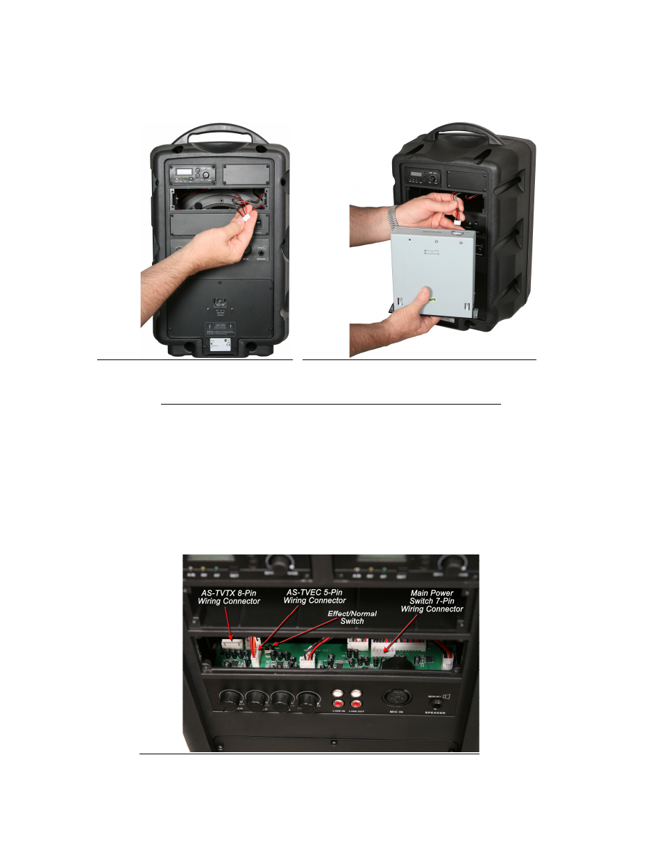
Photo 3.
Photo 4.
AS-TVTX Audio Link Transmitter and AS-TVEC Echo Module.
These two modules are to be installed only into the third bay down from the top. This
means that they cannot both be used simultaneously within the same Traveler. These
two module panels also contain the main Traveler power switch and charge LED.
This third bay down will always contain either one of these two modules or a panel
with only the main power switch and charge LED. Installation of these modules will
involve multi-pin connectors on the Traveler main circuit board. Photo 6 shows the
locations of these connectors on the main circuit board as seen through the third bay
opening.
Photo 6.
- CHECK MATE CM-130 (10 pages)
- CHECK MATE CM-140 (12 pages)
- CHECK MATE CM-150 (24 pages)
- CHECK MATE CM-200 (12 pages)
- CORE 12 (12 pages)
- FAROUTLET 300 S (16 pages)
- CORE X250 (16 pages)
- DS-CP22 (40 pages)
- DS-CP25 (40 pages)
- DS-EQ215 (20 pages)
- DS-EQ230 (40 pages)
- DS-SP24 (40 pages)
- DS-SP36 (40 pages)
- G-440 (16 pages)
- AS-HSA (4 pages)
- ESS (4 pages)
- HSE (2 pages)
- HSD (2 pages)
- HOT SPOT Handle Installation (2 pages)
- HOT SPOT User Guide (24 pages)
- HSVC Hotspot Yoke Bracket (6 pages)
- NSPA (24 pages)
- PA6S BOOM MOUNT KIT (3 pages)
- PA8X140 (12 pages)
- Setting up PA and Monitors (3 pages)
- CRICKET POLARITY TEST SET (14 pages)
- JIB/CT (12 pages)
- JIB/MM (8 pages)
- JIB/PA50 (8 pages)
- JIB/PB (2 pages)
- LA4/LA4PM Yoke Bracket (7 pages)
- LA4/LA4PM (8 pages)
- HDR2 (14 pages)
- RM-CDU (12 pages)
- GA64 / GA64SC (2 pages)
- RM2 (24 pages)
- RM-CD (5 pages)
- RM-CDV (7 pages)
- RM10 (12 pages)
- CK-HH (24 pages)
- TRAVELER AS-TV8 (36 pages)
- AS-M500 (22 pages)
- AS-QUAD (24 pages)
- CTS (20 pages)