Intermediate power drop on 1-light fixtures, Step 1. fixture modification, Is_f7000 – Philips IS-F7000 User Manual
Page 5: Philips, Lightoliièr, Lighting systems
Attention! The text in this document has been recognized automatically. To view the original document, you can use the "Original mode".
LIGHTOLIIÈR*
Lighting Systems
IS_F7000
Page 5 of 6
Instruction Sheet for Assembly and Installation of Pendant F7000
INTERMEDIATE POWER DROP ON 1-LIGHT FIXTURES
Step 1. Fixture Modification
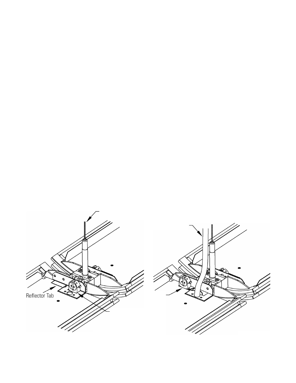
Once you have determined which fixture will be taking the in-line power drop, you need to remove the refiector and
lift the power-tray away from fixture to expose the thru-power harness. Next relocate the socket on socket-bracket
closest to where the power drop will take place. Fold-over tab on refiector to make room for socket. (Fig. 6)
Step 2. Power Splicing (where this is an additional drop)
Cut thru-power harness wires approximately 3" from end of fixture where splice is taking place. Cap wires coming
from pervious fixture. Route new power cord through the hole on power tray where the socket was relocated and
install the strain-relief at end of cord. Splice cord to thru-power harness making sure to match wire colors. Relocate
power-tray into housing making sure not to pinch any wires. (Fig. 7)
Step 3. Power Splicing (where this is the only power drop)
Route the new power cord through the hole on power tray where the socket was relocated and install the strain-
relief at end of the cord. Tap cord to thru-power harness making sure to match wire colors. Relocate power-tray into
housing making sure not to pinch any wires. (Fig. 7)
Aircraft Cable
New Power Drop
Socket
Figure 6
Relocated
Socket
Figure 7
631 Airport Road, Fall River, MA 02720 • (508) 679-8131 • Fax (508) 674-4710
We reserve the right to change details of design, materials and finish.
Lightolier is a Philips group brand
PHILIPS