Transmitter – Futaba 8SSHP User Manual
Page 5
•TRANSMITTER
This section explains the operation of the
transmitter controls when the servo reversing
switches are in the normal position. When the
reversing switches are in the reverse position,
servo operation is the opposite of that describ-
ed here.
1. AllerOn
Controls the ailerons.
2. ElevatOr
Controls the elevators.
3. Throttle Controls
the throttle.
4. Rudder Controls
the
rudders.
5. CH5 Switch
Controls the rate gyro output.
6. Hovering pitch lever Right side of transmitter.
•The hovering point pitch can be independently
adjusted without affecting the throttle.
•When the throttle lever 3 is near the center, the
pitch servo can be adjusted over approximately
20% of its total travel with this lever.
•When the throttle lever 3 is at the Low or High
side, this lever has no affect on the pitch servo,
even if it is moved.
High
Servo throw by
throttle lever
Low
Servo throw by
throttle trimming
(30% of total
travel)
12. Rudder trim lever
Rudder trimmer.
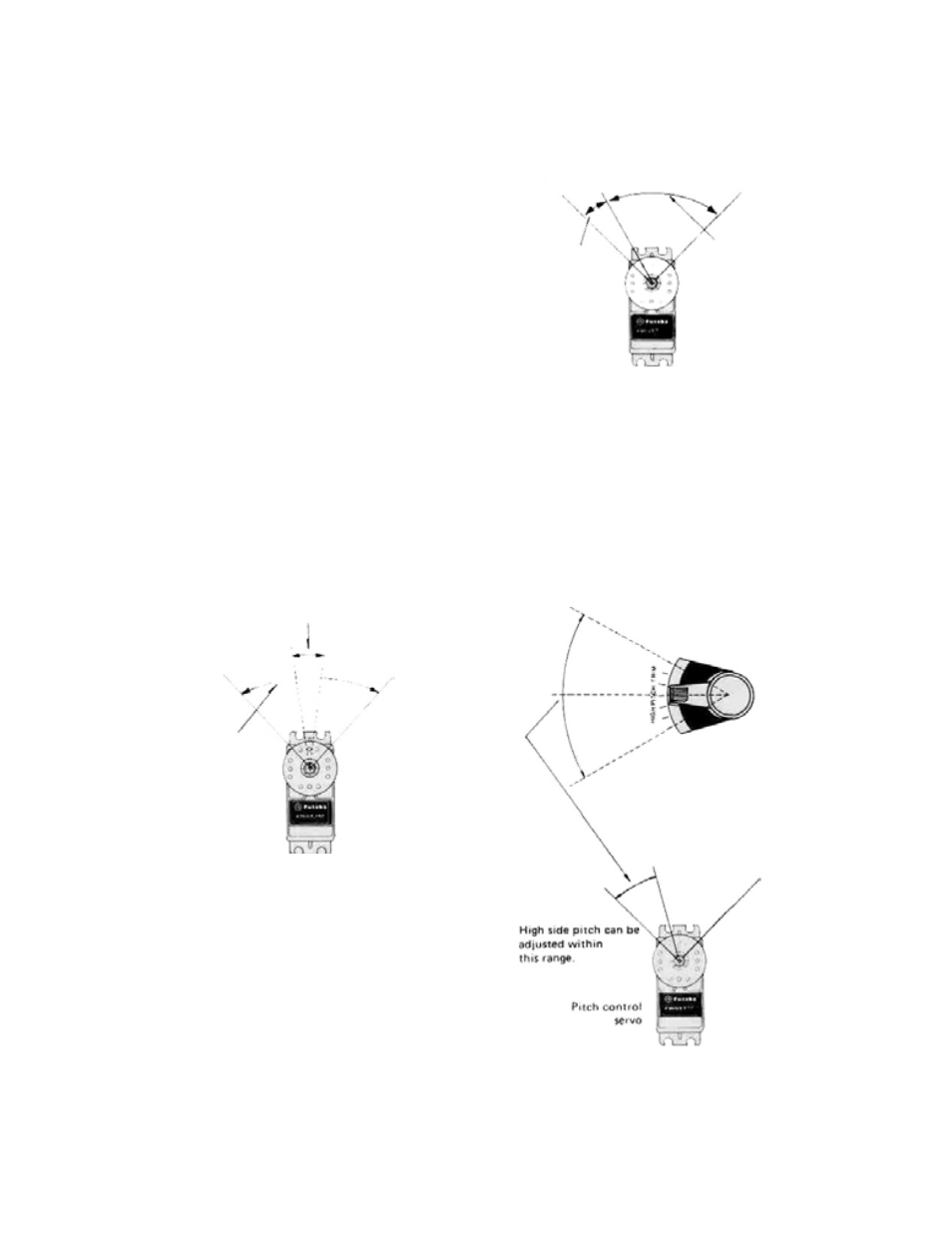
13. Pitch control HIGH side trim lever
(CH6), Right side of transmitter
Pitch control servo High pitch trimmer. The servo
throw can be adjusted from 0 to 30% of the total
3
servo travel. Set this lever for optimum pitch dur-
ing normal flight.
Fig. 5
Right-hand side of transmitter
When throttle lever is
at the center, adjustable within
this range with lever (6)
Pitch control servo
total travel
Pitch control servo
Fig. 4
7. CH7 knob Spare channel.
8. CH8 Switch Spare channel.
9. Aileron trim lever Aileron trimmer.
10.
Elevator trim
Elevator trimmer.
lever
11. Throttle trim lever w/ATL
Adjustable travel trim lever. This lever acts as a
trimmer only when the throttle lever is at the low
side as shown in Fig. 5. It is very convenient be-
cause the high side of the throttle position remains
unchanged even when the low side is adjusted.
Fig. 6