Grease duct standard connection – FloAire Non-Welded Grease Duct Systems User Manual
Page 6
6
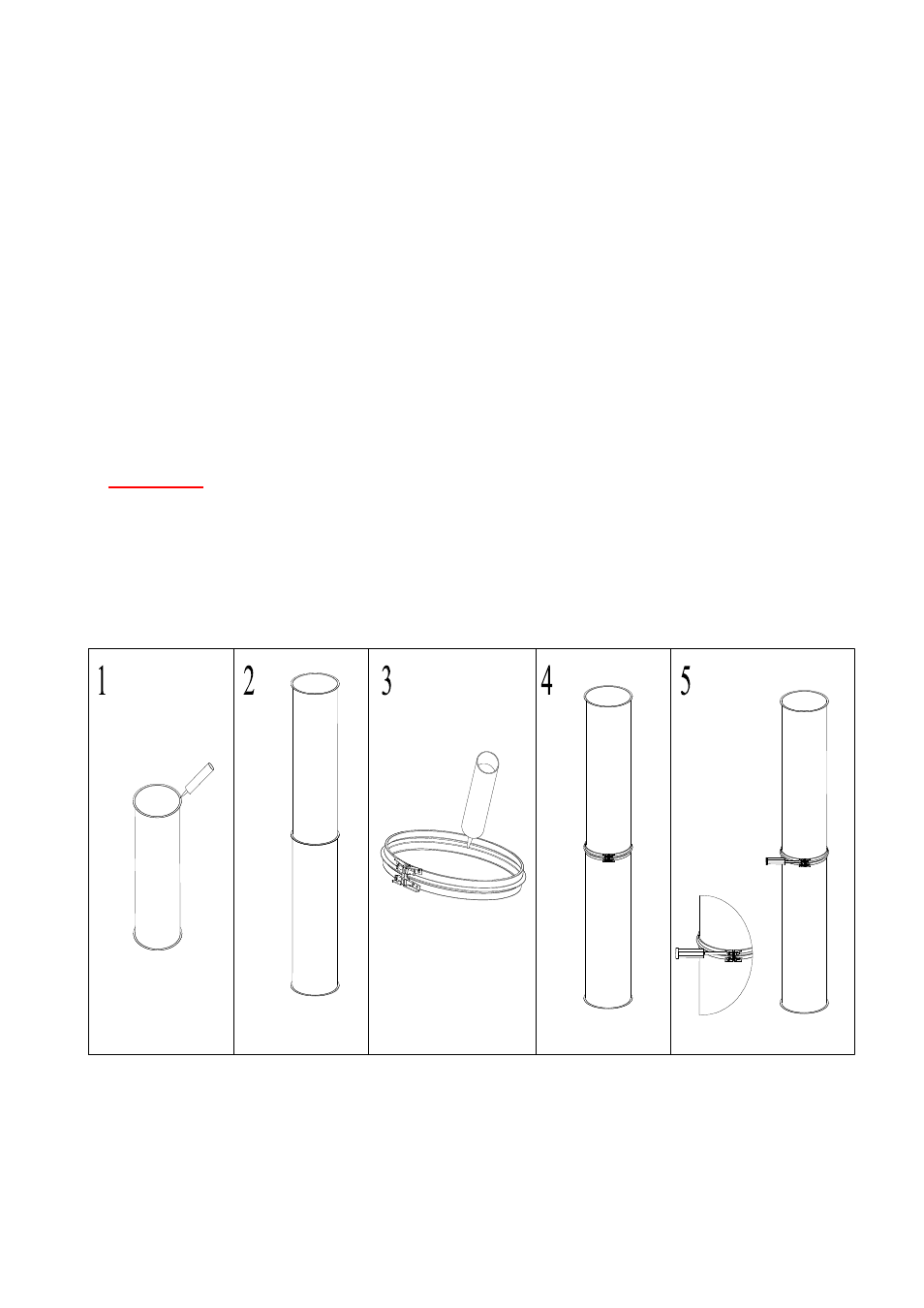
Grease Duct Standard Connection
1. Apply a continuous bead of proper sealant around the flange to be joined. The bead should be
¼” thick and continuous.
2. Join the two flanged ends of the duct section together.
3. Fill the “V” clamp with the proper sealant. The bead should be inside the “V”.
4. Install the “V” clamp around the duct sections. Both duct flanges should be inside the “V”.
5. For horizontal duct runs, the “V” clamp hardware should be located on the top side of the duct
and be orientated between the 3 and 9 o’clock position on the duct.
6. NEVER install the “V” clamp with the hardware orientated on the bottom side of the duct on
horizontal runs.
7. Secure the “V” clamp around the duct by tightening the ¼-20 hardware to 85 in-lbs.
8. See Fig. 1 below for details.
9. Remove any excess sealant from the inside of the duct surface.
IMPORTANT: THE HARDWARE USED TO ASSEMBLE THIS DUCTWORK IS SPECIFICALLY
DESIGNED FOR THIS APPLICATION. NO SUBSTITUTE HARDWARE IS ALLOWED. ALL
REPLACEMENT HARDWARE MUST BE PURCHASED FROM THE DUCTWORK FACTORY.
Fig.1 – Joint Assembly