Fan adapter plate, Alignment & bracing of grease duct – FloAire Non-Welded Grease Duct Systems User Manual
Page 11
11
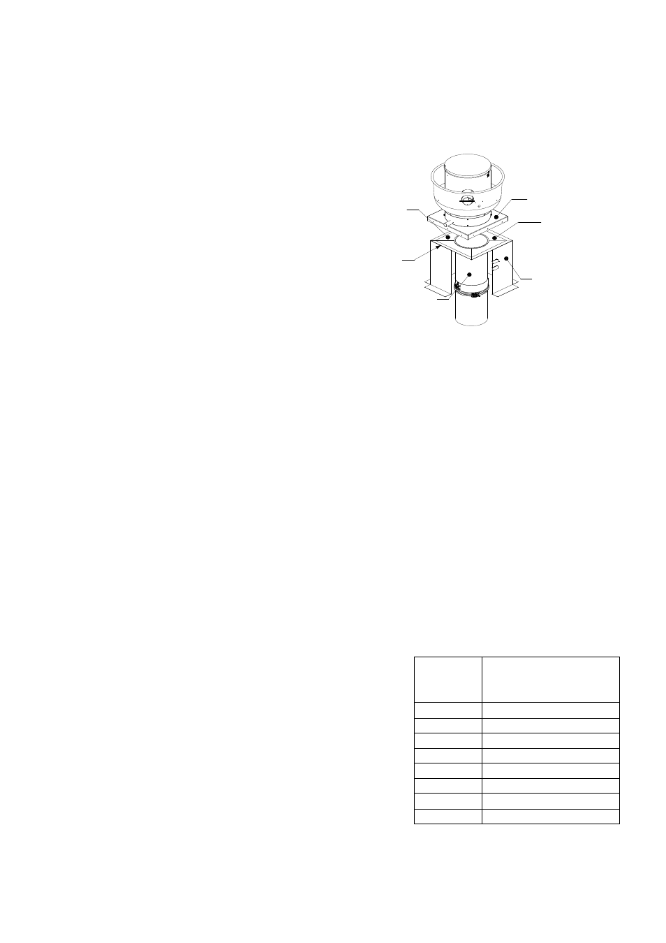
Fan Adapter Plate
The fan adapter plate (Transition Plate) is designed to
connect to a roof curb. The duct section is welded to
the underside of the adapter plate. The adapter plate
is formed to provide a slope to allow grease deposits
to flow back towards the duct. When connected, see
Fig. 7, the plate mounts on top of the fan curb, which
supports the fan housing. The plate may be
positioned off center within the curb provided that the
minimum distance to combustibles is maintained. In
the event that the plate is positioned off center, trim
off excess plate material to allow for fan placement.
Secure the plate to the curb using a minimum of three
fasteners per side. A suitably sized fastener provided
by others is used. The fan adapter plate can be used
to maintain distance to combustibles and also for
vertical support.
Prevention of Grease Accumulation in Horizontal Grease Duct
Duct systems serving Type 1 hoods shall be constructed and installed so that grease cannot collect in any
portion of the duct system. The duct system shall slope not less than ¼” per linear foot towards the hood or
toward an approved grease collection reservoir. Where horizontal ducts exceed 75 feet in length, the slope
shall not be less than 1” per linear foot. Offset collars have been designed to meet the above specification.
The collar is used in conjunction with other accessories such as tee’s and elbows to maintain the above
listed slope in horizontal duct runs. The “V” clamp hardware should be located on the top side of the duct and
be orientated between the 3 and 9 o’clock position on the duct. Never install the “V” clamp with the hardware
orientated on the bottom side of the duct on horizontal runs.
Alignment & Bracing of Grease Duct
Grease duct has the characteristics of a continuous stainless steel pipe and it will expand and contract along
its entire length with changes in its temperature. For this reason, conventional methods of attaching guides
and braces to the outer wall of the grease duct cannot be used. Correctly installed support rings, saddles
and wall guide assemblies will serve to keep the duct aligned, provide for adequate resistance to lateral
loads and allow the free axial expansion and contraction movement. A simplified rule for duct expansion is
that the axial growth will be approximately 1 inch per 100 feet of pipe length for each 100 degrees Fahrenheit
the exhaust vapor temperature is above the surrounding air temperature.
Horizontal Support & Support Spacing
Horizontal duct runs are supported using either 2 X 2 X 1/8” angle
or Unistrut, horizontal support spacing is shown in Table 3. When
cutting the angle or Unistrut to length there must be a minimum of 2”
on either side of the duct or duct wrap. It’s important that the 3/8”
threaded rod suspending the angle or Unistrut does not rub against
the duct or duct wrap. Once the angle has been cut to length it is
suspended using 3/8” threaded rod (minimum). Appropriate sized
holes are drilled/punched in either end of the angle. The 3/8”
threaded rod is secured to the angle or Unistrut using appropriate
sized hardware, washers are used on the top and bottom before
installing nuts, double nuts are used to make sure bottom nuts do not
come loose, see Fig. 8.
Fig. 7 – Fan Adapter Plate
Table 3 – Horizontal Support Spacing
DIAMETER
HORIZONTAL
SUPPORT SPACING
(FEET)
8"
10'
10"
10'
12"
10'
14"
10'
16"
10'
18"
10'
20"
10'
24"
10'
Adapter plate
Ceramic
gasket
(Optional)
Adjustable duct
Exhaust fan
Secured to
curb by others
Vented curb