Fig. 12 - grease duct installation guide, Grease duct installation – FloAire Non-Welded Grease Duct Systems User Manual
Page 16
16
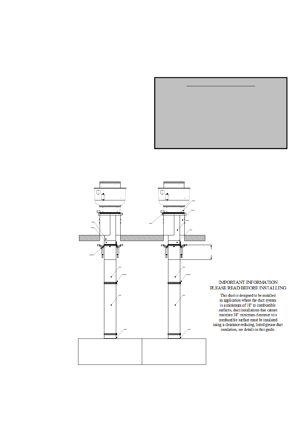
Fig. 12 - Grease Duct Installation Guide
Grease Duct Installation:
The illustration shown provides useful information on the
installation of grease duct systems. Each installation is
specific to the application and the job site. When duct
systems are installed outside, welded seams must be
painted with corrosion resistant high temperature paint. If
you encounter a situation not covered by this illustration,
refer to the guide or consult the factory. Remember, if the
distance to a combustible surface is less than 18 INCHES
you will need to wrap the duct in a listed duct wrap to get
“ZERO CLEARANCE TO COMBUSTIBLES”.
Adjustable ducts and standard
ducts can be used to terminate
at the transition plate. The duct
is fully welded to the transition
plate at the factory.
The vertical support assembly is
designed for 2" to 18" clearance
from duct to non-combustable
walls.
Adjustable ducts are used
on runs over 100 ft to compensate
for thermal expansion. The duct will
grow approximately 1" per 100 ft of
duct length for each 100 °F exhaust vapor
temperature above the surrounding air temperature.
The vertical support assembly is
mounted under the "V" clamp and
adjustable collar. This will allow
the vertical movement of the duct
system.
Adjustable duct
Riser
"V" Clamp
Standard duct
Standard duct
Adustable
collar
Fan adapter plate
with ceramic gasket
This duct is designed to be installed
in application where the duct system
is a minimum of 18" to combustible
surfaces, duct installations that can not
maintain 18" minimum clearance to a
combustible surface must be insulated
using a clearance reducing, listed grease duct
insulation, see details in this guide.
IMPOTANT INFORMATION
PLEASE READ BEFORE INSTALLING
"V" Clamp
Riser
Standard duct
Standard duct
See table 2
Adjustable duct
Vented curb per NFPA-96
Adustable
collar
Exhaust fan