Start-up procedure 80/20 – FloAire FAV-M User Manual
Page 18
18
START-UP PROCEDURE 80/20
Check for signs of damage. Do not operate if damage exists and contact your manufactures sales
representative. Units are easier to fix before the equipment is installed.
Check all installation clearances.
Clearance from Combustibles
Clearance for Serviceability
Top: 6” Sides: 6” Base: 0”
Unit: 24” Service Accesses: 48”
Check that the unit has been set level and secured.
Unit must have adequate structural support or the equipment or building may be damaged.
Curb and unit must be leveled or the unit may leak or be damaged.
Gasket and caulk the seam between the curb and unit base
Screw or weld the unit’s base to the curb
to avoid damage to the equipment.
Check that the accessories are set level and secured.
Accessories must have adequate structural support or the equipment or building may be damaged
Gasket, caulk, and screw each accessory to unit seam
Check that the unit’s intake and discharge are free of debris
Check that the filter are installed in the (optional) filter section or intake hood in accordance to the air
flow direction
Check that the unit’s ductwork size and length match the minimum ductwork size chart
Check that all field wiring has been completed in accordance to the factory supplied wiring diagram
Field wires are shown as dashed lines on the wiring prints
Check that all terminal screws are tight and that wires are in place
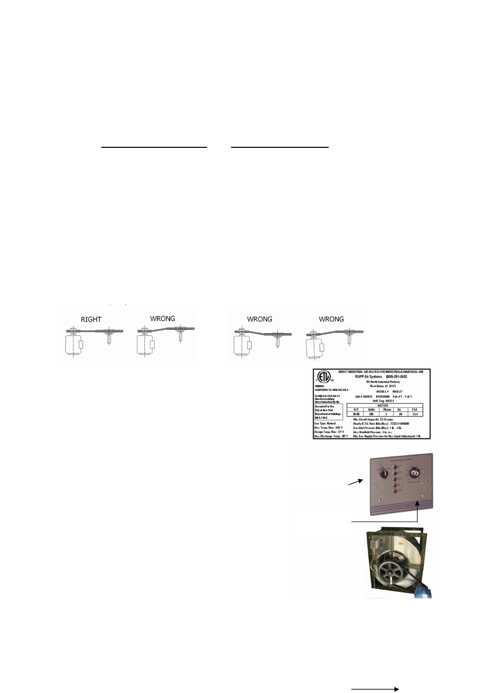
Check pulley alignment. Correct if necessary
Check that the power supply matches the nameplate
voltage, phase, and amperage
Record the voltage on the Start-Up Sheet
Check that the gas type and pressure matches the
nameplate type and pressure
Check that the gas type and pressure matches the
nameplate type and pressure
Contact the service department is the power or gas
supply needs to be changed in the field. Different parts
might be necessary for the change
Turn the Summer Off Winter switch to OFF
Set the Maxitrol Set-Point to the maximum
Turn the main power disconnect ON
Bump the blower motor starter to check the blower
wheel rotation
The decal is located on the blower housing
If the rotation is backwards turn off the power and
correct the wiring
The rotation can be corrected by interchanging two
legs of 3 phase power on the disconnect or blower
motor start contactor
SOW SWITCH
MAXITROL
SET-POINT
DIAL