Setup and calibration via serial interface, Troubleshooting – Flintec FAA-25 User Manual
Page 8
FAA-25 Technical Manual, Rev. 2.08 January 2012
Page 8 of 10
5.
Setup and Calibration via Serial Interface
If the FAA-25 amplifier includes an optional RS232C serial interface, you can perform eCal (electronic
calibration), normal calibration, adjust the filter, download setpoint values and indicate status information by
using the xFace software installed on a PC (valid for device serial no. J800110831 or higher; older devices
require the eCal-Transmitter software).
The minimum PC requirements are: MS Windows XP or Vista operating system
RS232C serial interface
Serial cable for RS232C signals between FAA-25 and PC
The xFace software for installation can be found on the Flintec CD-ROM in the directory “Software\Software for
Flintec Products\FAA-25“.
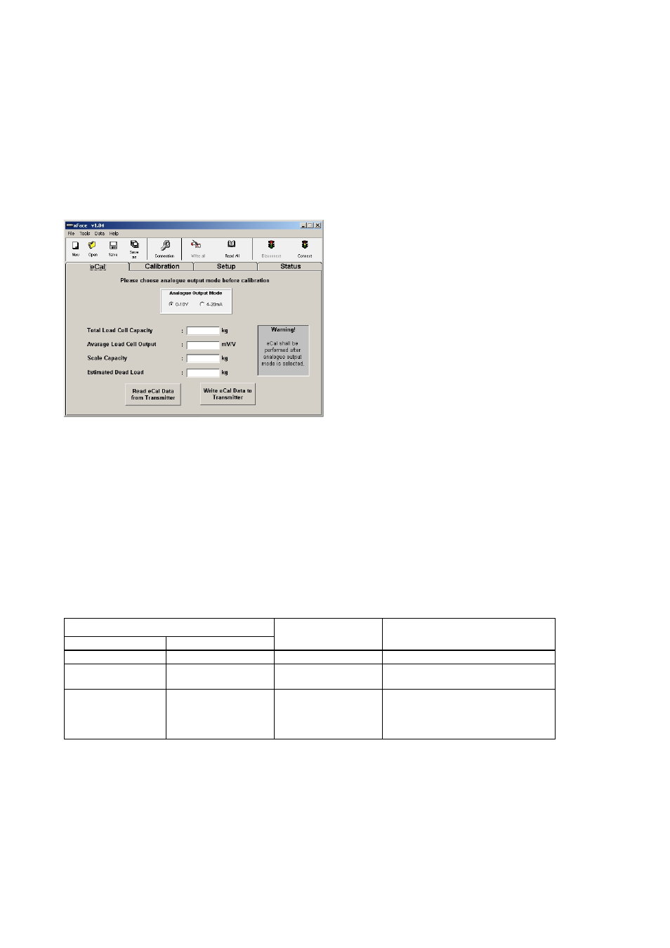
The main tab of this software is shown at the left.
eCal is made very easy:
1. Enter the total load cell capacity in [kg], the averaged
load cell’s rated output in [mV/V], the scale capacity in
[kg] and the estimated dead load value in [kg] into the
eCal window.
2. Click the button “Write eCal Data to Transmitter”.
After performing eCal as described in the software manual, check the performance of your system. After you
have assured the accuracy of the system you can use it. You can find essential information for using the xFace
software in its help file.
6. Troubleshooting
The type FAA25 amplifier has been designed as a very reliable and virtually error free instrument. However if an
error occurs do not attempt to repair the equipment before you understand what caused the error. Note the
status of the front panel LEDs, and try to find the problem with the help of the table given below. Don’t let
unauthorized people interfere with the instrument.
In case of an error the ERR LED indicates the analogue output mode like the RUN LED.
If the output mode is set to 4 -20 mA, the ERR LED lights continuously in case of an error. If the analogue
output mode is set to 0 – 10 V, the ERROR LED flashes.
FRONT PANEL LEDS
ERROR OUTPUT
(Option)
DEFINITION
Green RUN LED
Red ERROR LED
On / Flashing
Off
1
Normal
operation
Off Off 0
No
power
Board
failure
Off
On / Flashing
0
Input signal is out of range
Calibration
needed
Check output circuit & cables
Board
failure
The analogue output also gives additional information about the weighing system as described in chapter 3.
If the calibration was done wrong (e.g. the adjustment of the zero and the span was done with the same load by
accident) then following procedure has to be done:
1. De-power FAA-25 and re-power it again.
2. Switch the analogue output to the other non-active output mode.
3. Perform a „rough“ zero and span adjustment according chapter 4.2.2 respective chapter 5.
4. Switch the analogue output back to the wished output mode.
5. Perform a proper adjustment according chapter 4.2.2 respective chapter 5.