Operation, Setup and calibration by using the key buttons, Setup of the analogue output mode – Flintec FAA-25 User Manual
Page 6: Setup and calibration
FAA-25 Technical Manual, Rev. 2.08 January 2012
Page 6 of 10
3. Operation
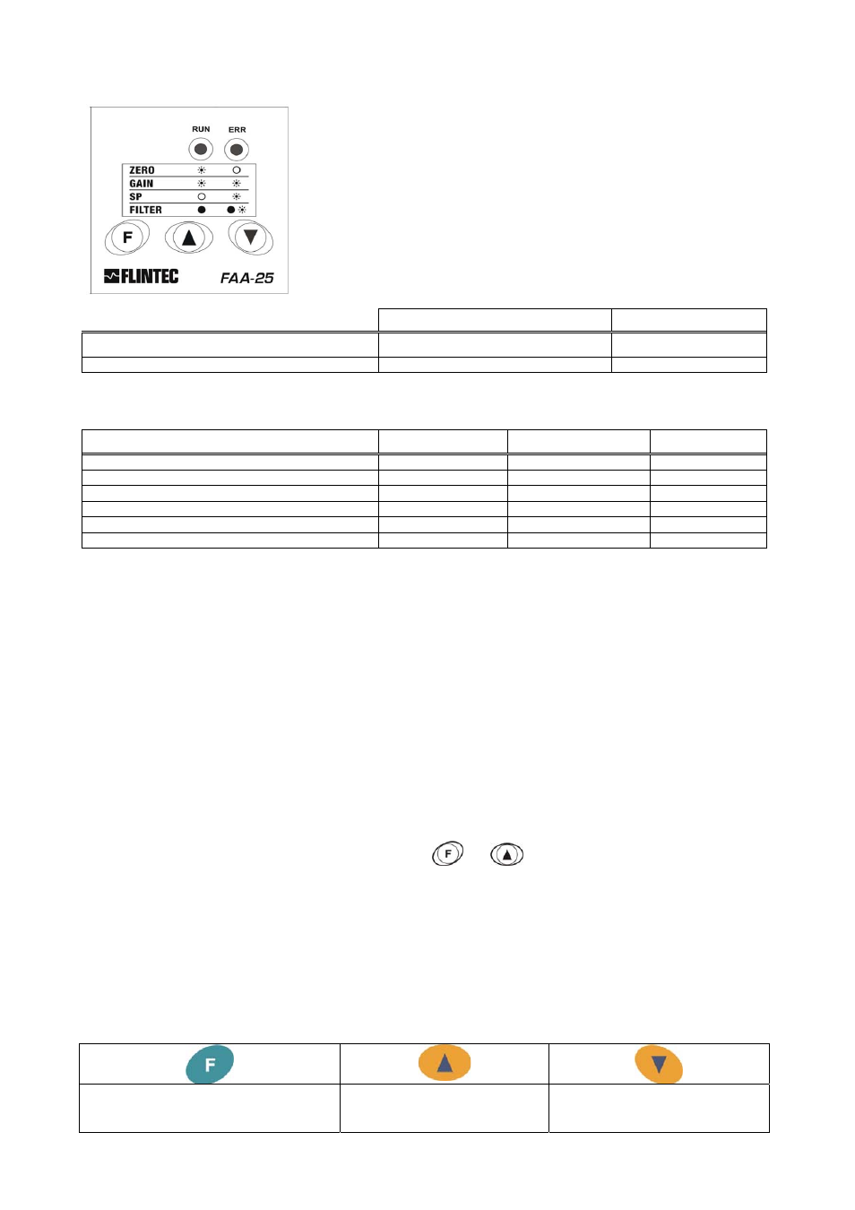
There are 2 LEDs and 3 keys on the front panel of FAA-25. The
keys are used for setup and adjustments and the LEDs have
different meaning in operation and setup mode. The usage of the
keys is described in chapter 4.
In operation mode with connected electrical load the green RUN
LED is on and the red ERROR LED is off. See chapter 6 in case of
the red LED turns on.
The status of the LEDs during normal operation is given in the table
below.
In normal operation
0 – 10 V output
4 – 20 mA output
Green RUN LED
Flashes (on for 4 seconds)
On
Red ERROR LED
Off
Off
For troubleshooting see chapter 6.
The analogue output signal gives information about the status of the system and the weighing process:
Condition
0 – 10 V output
4 – 20 mA output
Error (option)
Operation X
X
High
Setup X
X
Low
Weight is higher than the range (Over)
13 V
24 mA
Low
Weight is lower than the zero range (Under)
-1.4 V
0 mA
Low
System Error
13 V
24 mA
Low
ADC is out of operating range
-1.4 V
0 mA
Low
4.
Setup and Calibration by using the Key Buttons
During the power on period the green and red LEDs are lightened for 3 seconds. After both LEDs turned off for
a short period, one of them will be lightened. If you did not follow this LED signalization sequence, power off the
instrument, check the power and the load cell cables and power it on again.
In this step the lightened LED informs you about the active analogue output mode of the instrument. If the green
RUN LED is continuously lightened, the analogue output mode is 4 – 20 mA; if it flashes, the analogue output
mode is 0 – 10 V (the electrical load should be connected before). If the planned usage is different from the
active mode, you have to select the analogue output mode first, see Chapter 4.1.
After this the instrument is set up and calibrate as described in Chapter 4.2.
Finally check the performance of your system with different test weights. After being sure of the accuracy of the
system you can use it.
4.1. Setup of the Analogue Output Mode
The selected analogue output mode (voltage or current) is indicated by the RUN LED and the ERROR LED as
described in chapter 3.
If you want to change the analogue output mode press
and
keys simultaneously.
If you have changed the analogue output mode, you have to recalibrate the transmitter – regardless if it
has already been calibrated for the other output mode.
4.2. Setup and Calibration
Warning: The analogue output mode shall be selected as 0 – 10 V or 4 – 20 mA before the calibration.
Do not forget to calibrate the instrument after changing the analogue output mode.
In this chapter you will find the required information for the setup and the calibration of FAA-25. The symbols at
the right bottom of the keys show the function of the keys in setup mode. The meanings of the keys in the setup
mode are given in the table below.
Enter / exit the setup mode
Go to the next step
Save
Increase the value
Setup Setpoint no. 1
Filter type “High”
Decrease the value
Setup Setpoint no. 2
Filter type “Low”