Features, Technical specification, Housing dimensions – Flintec FAA-25 User Manual
Page 3
FAA-25 Technical Manual, Rev. 2.08 January 2012
Page 3 of 10
1. Features
The amplifier type FAA-25 is an accurate and economic load cell transmitter, easy to integrate into process
controll systems. By its “digital heart” – modern microcontroller technology – type FAA-25 allows a comfortable
calibration and setup with a combination of LED’s and push buttons.
The analogue signal output is programmable to 0 – 10 V and 4 – 20 mA.
An opto-isolated interface option offers two setpoints, one error output, one input for zeroing by external
command and one RS232C serial interface for setup and electronic calibration (PC software “xFace”).
1.1. Technical
Specification
INPUT & A/D CONVERTER
Linearity
0.01 % or better
Analogue input range
0 mV to 20 mV
Min. input range
< 1 mV
A/D converter
24 bit Delta-Sigma ratiometric with integral analog and digital filters
Resolution
Min. 0.1 μV/d
Internal resolution
Min. 8 million counts
Conversion rate
Up to 100 measurement values per second
SCALE CALIBRATION & ANALOGUE OUTPUT
Calibration
Performed with keys. There is no switch or resistor for adjustment in the instrument;
alternatively by PC-software (option board required)
Digital filter
2 step adjustable digital adaptive filter
Weighing functions
Zeroing via opto-isolated digital input (option board required);
max. zeroing range is 30% of weighing range
D/A converter
16 bit
Analogue output
Current output 4-20 mA (at max. 500 load) or
voltage output 0-10 V (at min. 10 k load)
Set points
2 programmable free setpoints (option board required)
LOAD CELLS
Excitation
5 V DC
Number of load cells
Up to 4 units of 350 or 12 units of 1100 (min. 85 )
Connection
4 or 6 wire technique. Cable length 274 m/mm² for 6 wire connection
SETUP & COMMUNICATION
Front panel
Membrane keypad including 2x LED and 3x programming keys
eCal
Electronic calibration without test weights using PC software (option board required)
POWER
Power supply
24 V DC (18…30 V DC), 200 mA
ENVIRONMENT AND ENCLOSURE
Operation temperature
Between -10 °C and +40 °C at 85% RH max, non-condensing
Enclosure
Polyamide, for DIN-rail mount, IP20
OPTION
Interface option
2 opto-isolated outputs for 2 setpoints, 1 opto-isolated error output, 1 opto-isolated input for
zeroing and 1 RS232C serial interface
Characteristics of digital
outputs
NPN open collector; 18…30 V DC, max. 50 mA
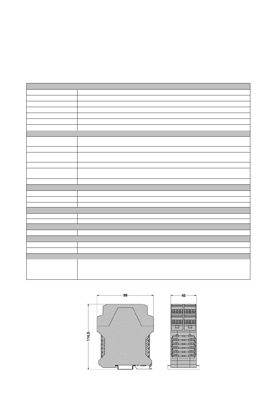
1.2. Housing
Dimensions