Load cell connection, Analogue output connection, Optional digital inputs / outputs – Flintec FAA-25 User Manual
Page 5: Optional rs232c serial interface, Commissioning
FAA-25 Technical Manual, Rev. 2.08 January 2012
Page 5 of 10
2.3.
Load Cell Connection
The load cell wiring should be made carefully before energizing to avoid damages to the instrument and the
load cells. The input resistance of the load cells that you want to connect should be more than 85 Ω.
The sense pins of the instrument must absolutely be connected. In 4-wire installations the sense and the
excitation pins with the same polarity should be short circuited at the connector side.
Pin
6-wire Load Cell Connection
4-wire Load Cell Connection
+ Ex
+ Excitation
+ Excitation
+ Se
+ Sense
+ Excitation
- Se
- Sense
- Excitation
- Ex
- Excitation
- Excitation
+ Si
+ Signal
+ Signal
- Si
- Signal
- Signal
Shield Shield
2.4.
Analogue Output Connection
There are 2 analogue outputs on FAA-25, one is for 0 – 10 volt and the other for 4 – 20 mA. But only one of
them can be used at the same time and has to be selected in the setup mode.
The wiring of the analogue output should be done according to the pin configuration given in the table below.
Pin Definition
V
0 – 10 V output (+ Signal)
I
0 – 20 mA output (+ Signal)
G
GND (- Signal)
Shield
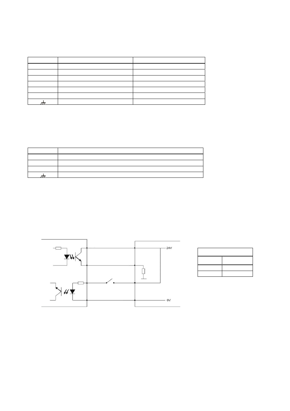
2.5. Optional Digital Inputs / Outputs
Optionally two setpoint outputs, one error output and one zeroing input can be added to type FAA-25.
If an input signal is supplied to the zeroing input, the analogue output signal of FAA-25 will be set to “0 kg”.
The setpoints will be active when the weight value is higher than the entered setpoint value.
If any failure occurs within FAA-25, an error output will be indicated with the LED on the front panel.
If you want to use these I/O, prepare the circuits as shown below.
Figure 2.
Optional digital I/O connection diagram and error output description
2.6. Optional RS232C Serial Interface
The optional serial interface can be used for eCAL (electronic calibration), adjusting filters, entering setpoint
values, exporting status information, etc. The pin configuration is shown in Figure 1.
2.7. Commissioning
After making the connections of FAA-25 as described above, energize FAA-25 carefully. Then set the
instrument to the desired analogue output mode and perform the setup and calibration operations.
Check the performance of your system with different test weights. After you have assured the accuracy of the
system you can use it.
Error Output
Status Definition
1 OK
0 Error
+Vc
Zero
Error or setpoint
Common
R
load