Installation and commissioning, Mechanical installation, Electrical connections – Flintec FAA-25 User Manual
Page 4
FAA-25 Technical Manual, Rev. 2.08 January 2012
Page 4 of 10
2.
Installation and Commissioning
PRECAUTION:
Please read this manual carefully before energizing the amplifier and perform the commission-
ing operation according the procedure given here. Use trained personnel for commissioning, checking and
service of the instrument. The interference of untrained personnel may cause unwanted damages or injures.
2.1.
Mechanical Installation
First of all please determine the place where your instrument can operate safely. The place where you will
use/install your instrument should be clean, not getting direct sunlight if possible, with a temperature between -
10ºC and +40ºC, 85% maximum relative humidity non-condensing.
The cables should be installed safely to avoid mechanical damages.
Take care to the housing dimensions given in chapter 1.2. To avoid electrical noise protect your transmitter
which has very low input signal level, from the equipment that produces electrical noise.
Place your transmitter in a separate panel from the frequency converters and motor contactors, or at least place
it in another partition of the panel. Do not combine signal cables and power cables in cable trays. And check
that the cables are wired properly in order to prevent mechanical damage.
2.2.
Electrical Connections
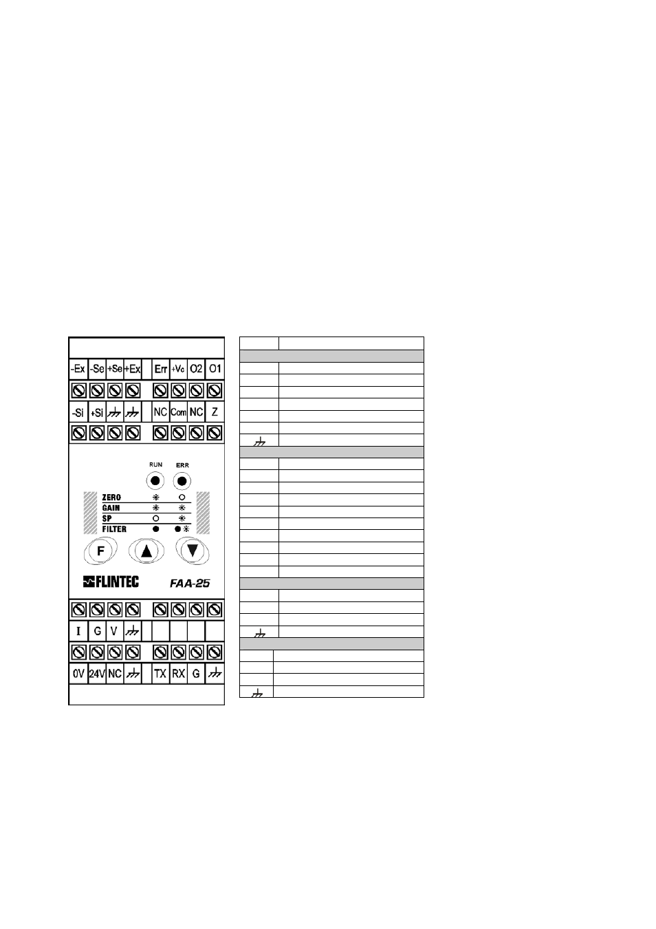
The pin layout of FAA-25 is shown below. Electrical connections should be done carefully. FAA-25 requires a
power supply of 230 V AC (50 Hz, 6 VA, see figure 1) or 24 V DC (200 mA, see figure 2 ) to operate.
The meanings of the pins are:
Pin Definition
LOAD CELL CONNECTION
- Ex
- Excitation
- Se
- Sense
+ Se
+ Sense
+ Ex
+ Excitation
- Si
- Signal
+ Si
+ Signal
Shield
DIGITAL I/O OPTION
Err Error
output
+ Vc Common +24V DC for outputs
O1
Digital output no. 1
O2
Digital output no. 2
NC Not
Connected
Com Zeroing input (0 V)
Z
Zeroing input (+24 V)
TX
Transmit (RS232C)
RX
Receive (RS232C)
G
Ground (RS232C)
ANALOGUE OUTPUT
I
0 - 20mA output (+ Signal)
G
GND (- Signal)
V
0 - 10V output (+Signal)
Shield
NETZANSCHLUSS
0V
0 V
24V
24 V DC
NC Not
Connected
Shield
Figure 1:
FAA-25, front view
and pin layout
Do not forget to connect the shield of the load cell cable and the analogue output cable to FAA-25 at the
correct ground terminals.
The quality of the grounding of your system provides the accuracy of your weighing system beside it’s safety. If
the condition of the power line in the plant is bad, prepare a special power line and grounding.
If you have to service the instrument, turn off the power and wait at least for 30 seconds before interfering.
Perform the other connections to FAA-25 as described below.