Twisted pair cabling -12 – Cabletron Systems HSIM-FE6 User Manual
Page 30
Chapter 2: Installation
2-12
HSIM-FE6 User’s Guide
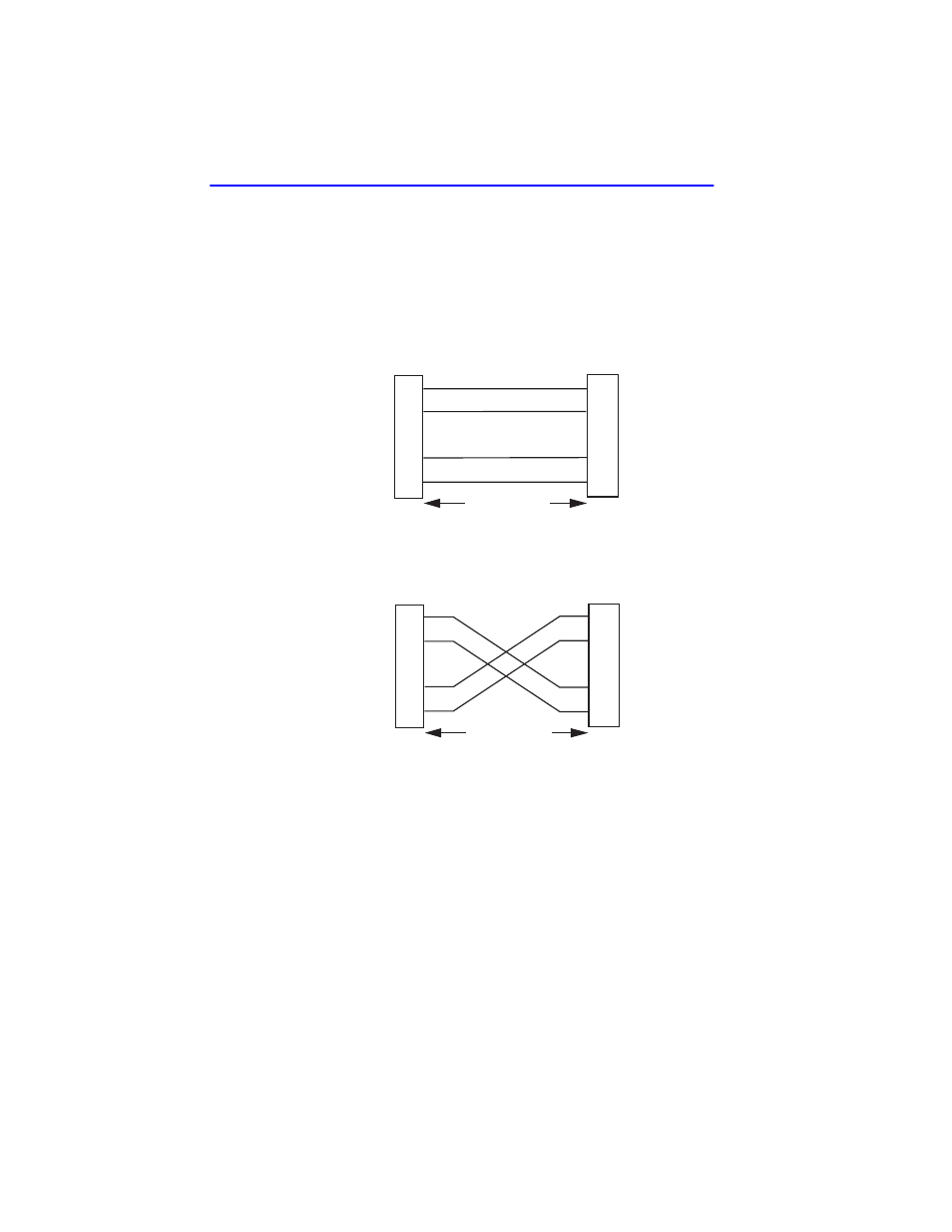
A schematic of a straight-through and a crossover cable is shown in
. If the wires do not cross over, use the switch on the FE-100TX
to internally cross over the RJ45 port.
shows how to properly
set the FE-100TX crossover switch.
Figure 2-6
Twisted Pair Cabling
Connect an FE-100TX to a twisted pair segment as follows:
1.
Ensure that the device connected to the other end of the segment is
powered ON.
2.
Connect the twisted pair segment to the module by inserting the RJ45
connector on the twisted pair cable into the RJ45 port on the module
shown in
.
TX+
TX–
RX+
RX–
2
1
3
6
TX+
TX–
2
1
3
6
NOTE:
RX+/RX– and TX+/TX–
must share a common
color pair.
TO
RJ45 Port
25041-08
RJ45 to RJ45
RX+
RX–
TX+
TX–
RX+
RX–
2
1
3
6
TO
10BASE-T or 100BASE-TX
Device Port
TX+
TX–
2
1
3
6
RJ45 to RJ45
RX+
RX–
TO
RJ45 Port
Straight-Through Cable
Crossover Cable
TO
10BASE-T or 100BASE-TX
Device Port
- FOT-F3 (41 pages)
- FOT-F3 (44 pages)
- BRIM-F6 (41 pages)
- WPIM-RT1 (50 pages)
- BRIM-WT1 (32 pages)
- 36 (33 pages)
- 9T101-04 (28 pages)
- FDDI Repeater (29 pages)
- SWPIM-BRI (34 pages)
- 9C114 (26 pages)
- SMARTSWITCH ROUTER 9032578-05 (398 pages)
- HSIM-W6 (258 pages)
- NB25 E (30 pages)
- HSIM-G01 (36 pages)
- Expansion module 9E429-36 (18 pages)
- EMM-E6 Ethernet (205 pages)
- Environmental Module TM 9C300-1 (50 pages)
- CSMIM-T1 (198 pages)
- NBR-620 (73 pages)
- E2100 (42 pages)
- KBU64 Rackmount (26 pages)
- AirConnect 3Com (93 pages)
- 802.1Q (92 pages)
- W85 (60 pages)
- ELS10-26 (170 pages)
- Expansion module 9E106-06 (40 pages)
- 6H259-17 (58 pages)
- Expansion module 9F120-08 (12 pages)
- EMC39-12 (33 pages)
- 6A000/ZX-250 (268 pages)
- Expansion module DELHE-UA (50 pages)
- Expansion module 9T122-08 (36 pages)
- DMS-100 (196 pages)
- BRIM E100 BRIM-E100 (42 pages)
- Cabletron CyberSWITCH CSX400 (275 pages)
- Cabletron SmartSwitch Router 250 (34 pages)
- Network Router (100 pages)
- 9W111-08 (28 pages)
- CSX400 (101 pages)
- Cabletron SmartSwitch Router 510 (106 pages)
- SEHI-32/34 (90 pages)
- SmartSwitch (338 pages)
- 9T106-01 (28 pages)
- Switch 9H531-17 (38 pages)