Upper stage stage engine mount installation, Attach upper stage fins, Attach launch lug and apply glue fillets – Estes 2109 - Renegade User Manual
Page 2: Install nose weight, Install shock cord mount, Booster stage engine mount assembly, Prepare booster tubes, Parts, Parts bt-20 bt-60
11.
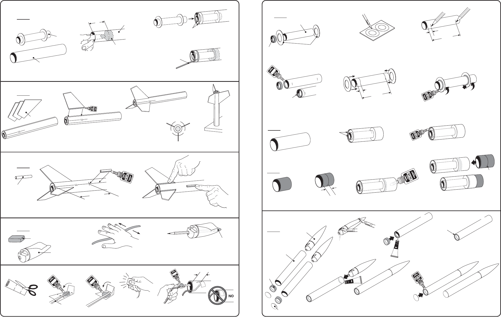
UPPER STAGE STAGE ENGINE MOUNT INSTALLATION
FRONT
UPPER BODY
TUBE ASSEMBLY
PARTS
ENGINE MOUNT ASSEMBLY
A.
Use finger to smear glue 2” (51 mm)
inside upper stage body tube.
B.
Insert engine mount until flush with end.
Let dry.
C.
Use a scrap piece of balsa to apply a glue fillet between
the centering ring and body tube joint. Let dry.
12.
ATTACH UPPER STAGE FINS
PARTS
UPPER BODY TUBE
A.
Apply thin layer of glue to lower
fin, wait 1 minute. Apply 2nd thin
layer and attach fin centered on
fin line even with end of body tube.
Let dry
.
B.
Repeat for
remaining fins.
Let dry.
120˚
120˚
120˚
NOTE:
FINS MUST BE ATTACHED
CORRECTLY FOR A
STABLE FLIGHT.
SCRAP BALSA
13.
ATTACH LAUNCH LUG AND APPLY GLUE FILLETS
PARTS
LAUNCH LUG
A.
Mark Launch lug line at 4 1/4” (108 mm).
Glue launch lug centered on “LL” line even
with mark. Let dry.
B.
Apply glue fillets to all
fin and launch lug/body
tube joints. Let dry.
GLU
E
1”
(25 mm)
A.
Cut out shock cord
mount from top of
page 2.
B.
Apply glue.
fold foreward.
C.
Apply glue.
Fold forward.
D.
Squeeze tightly
and hold for one
minute
.
E.
Glue mount 1” (25 mm) inside upper stage
body tube. Hold until glue sets. Let dry.
SHOCK CORD
14.
INSTALL NOSE WEIGHT
15.
INSTALL SHOCK CORD MOUNT
PARTS
CLAY WEIGHT
A.
Form the clay weight
into a thin snake.
B.
Use a long wooden pencil to
tamp the clay into the front of
the nose cone as far as
possible.
Use all of the clay.
C.
Apply a ring of glue just inside the
end of the tube, insert the adapter
ring until flush with end. Let dry.
3.
BOOSTER STAGE ENGINE MOUNT ASSEMBLY
DIE CUT
CENTERING
RINGS
ADAPTER
RING RA-520
GREEN
ENGINE MOUNT TUBE
A.
Carefully remove centering
rings from card using a
modeling knife.
D.
Push the centering rings onto the tube,
at 1/8” (3 mm) and 2 1/2” (64 mm)
marks.
PARTS
B.
Mark tube at the 1/8” (3 mm) mark
and 2 1/2” (64 mm) mark from end.
E.
Apply glue fillets to both
sides of each ring. Let dry.
PARTS
BT-20
BT-60
BOOSTER STAGE
BODY TUBE.
PARTS
RED TUBE COUPLER
F.
Insert engine mount until the
motor tube is flush with the end
.
FLUSH
G.
Apply a glue fillet to the inside
ring/body tube joint. Let dry.
H.
Mark red tube coupler
at 3/4” (19 mm).
I.
Apply a ring of glue inside the
front of booster tube at the body
tube/centering ring joint.
J.
Insert red adapter into booster
tube up to the 3/4” (19 mm) mark.
Let dry.
4.
PREPARE BOOSTER TUBES
PARTS
A.
Remove flash from
nose cones using
a modeling knife.
B.
Apply a ring of glue
just inside end of tube.
Insert adapter ring
flush with end. Let dry.
C.
Repeat for 2nd
tube. Let dry.
FLUSH
D.
Apply a ring of cement inside front of
body tubes. Insert nose cone.
Let dry. Repeat for 2nd tube. Let dry
.
P
L
A
S
TIC
C
EM
E
N
T
E.
Apply glue to end of tube and press disc in
place. Let dry. Repeat for 2nd tube. Let dry.
COMPLETED BOOSTER
TUBE ASSEMBLY.
FRONT
page 6
COMPLETED
ASSEMBLY
NOSE CONE (2)
PNC-50KA
BODY TUBE (2)
BT-50
GREEN
ADAPTER
RINGS (2)
RA-2050
DISCS (2)
page 3
PLASTIC
CEMENT
FRONT
3/4”
(19 mm)
3/4”
(19 mm)
FRONT
2 1/2”
(64 mm)
1/8”
(3 mm)
FRONT
FRONT
FLUSH
G
LU
E
2 1/2”
(64 mm)
1/8”
(3 mm)
FRONT
ENDS FLUSH
2”
(51 mm)
REAR
GLUE
BODY TUBE
FINS
CLAY
NOSE CONE
4 1/4”
(108 mm)
END VIEW
C.
Stand rocket on
flat table until glue
dries completely.
S
H
O
C
K
C
O
R
D
M
O
U
N
T
S
E
C
T
IO
N
3
S
E
C
T
IO
N
2
S
E
C
T
IO
N
1
3
G
LU
E
3
2
1
G
LU
E