Assemble stabilizer (continued.), Assemble stabilizer (continued), Attach rudder – Estes 1265 – Scissor Wing Transport User Manual
Page 6: Install nose cone insert
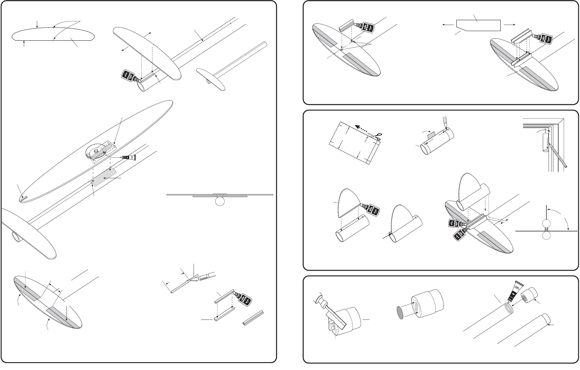
5/16"
(8 mm)
ELEVATOR
NOTCHED END
TO REAR
PIVOT BASE
9" (22.9 cm)
6.
7.
C. Apply a line of glue onto the
alignment line up to the 1-1/2"
(3.8 cm)
mark. Align marks on
Stabilizer with line on Body
Tube and position Stabilizer
even with end of body tube.
Let dry.
6. ASSEMBLE STABILIZER (Continued.)
D. Apply band of cement to under side of
Plastic Pivot Base as shown. Glue Wing
Assembly to body tube centered on
reference line with rear of Pivot Base
at the 9"
(22.9 cm)
mark.
E. Attach Elevator to Stabilizer using self-adhesive Tape
Hinges from decal sheet. Fold Elevator up and back
several times to crease hinges and to insure proper
operation.
F. Cut a a piece of the Launch Lug to 1-3/8"
(3.5 cm)
long. Glue launch lug to wide side of Tube Mount
Spacer. Let dry.
ALIGNMENT MARKS
CURVED
STRAIGHT
11/2"
(3.8 cm)
MARK
ALIGNMENT LINE
COMPLETED
ASSEMBLY
G. Glue tube mount spacer to main portion of stabilizer.
Center on alignment marks as shown.
6. ASSEMBLE STABILIZER (Continued)
NOTE: Do not put glue
on slant edge
or on elevator.
ALIGNMENT
MARKS
A. Cut out Rudder
Mount Tube Marking
Guide from page 2.
RUDDER
7. ATTACH RUDDER
B. Wrap guide around Rudder Tube,
secure with tape. Mark tube at
arrow points put an "R" at rudder
line and "TM" at tube mount line.
D. Apply glue to Rudder and attach to Rudder
tube. Center on rudder line flush with rear
of tube. Let dry.
E. Glue Rudder Assembly to Tube Mount. Front of
tube should be 5/16"
(8 mm)
forward of front of
Tube Mount. Center at 90ß angle to Stabilizer.
A. Using a razor saw, carefully cut
off eyelet flush with end. Sand
as required for a flat surface area.
NOSE
CONE
INSERT
8. INSTALL NOSE CONE INSERT
B. Locate and remove red
Engine Debris Block
from decal sheet. Center
over end of insert and
press into place.
COMPLETED
ASSEMBLY
CURVED
STRAIGHT
STABILIZER
ROTATE WING 90ß, MAKE SURE WING
IS PARALLEL TO STABILIZER. ALLOW
CEMENT TO DRY COMPLETELY.
REAR VIEW
TAPE HINGE
1"
(2.5 cm)
SPACE
LAUNCH LUG
1-3/8"
(3.5 cm)
TUBE MOUNT
SPACER FROM
1/8" (3 mm)
SHEET
LAUNCH LUG
TUBE MOUNT
SLANT
FRONT
REAR
H. Glue a Tube Mount to each side of Tube Mount
Spacer. Position as shown. Elevator must be
free to raise slightly. Let dry.
C. Remove marking
guide. Extend all
lines entire length
of tube.
DOOR
FRAME
FLUSH
FRONT OF BODY
TUBE/WING ASSEMBLY
SHOULDER
SHOULDER
FLUSH
WITH END
C. Apply plastic cement inside front of Body Tube. Push
insert in until shoulder is flush with tube end. Let dry.
REAR
90ß
REAR VIEW
USE SANDPAPER TO
ROUGHEN TUBE
SURFACE AREA WHERE
PIVOT BASE MOUNTS
FOR A BETTER
CEMENT BOND.
TAPE HINGE
RU
D
DER
MOU
NT
TUB
E
R
U
D
D
E
R
M
O
U
N
T
T
U
B
E
M
A
R
K
IN
G
G
U
ID
E
RUDDER
TUBE
RU
DDER
TAPE
RUDDER MOUNT
TUBE MARKING GUIDE