Diesel powered operating controls – EDCO SS-26E User Manual
Page 6
E-SS2636-DGE-I-1012
Printed in USA
©2012
TVW
Page 6
100 Thomas Johnson Drive, Frederick, MD 21702-4600 USA
Phone (301) 663-1600 • 1-800-638-3326
Fax (301) 663-1607 • 1-800-447-3326
Website: www.edcoinc.com • Email: [email protected]
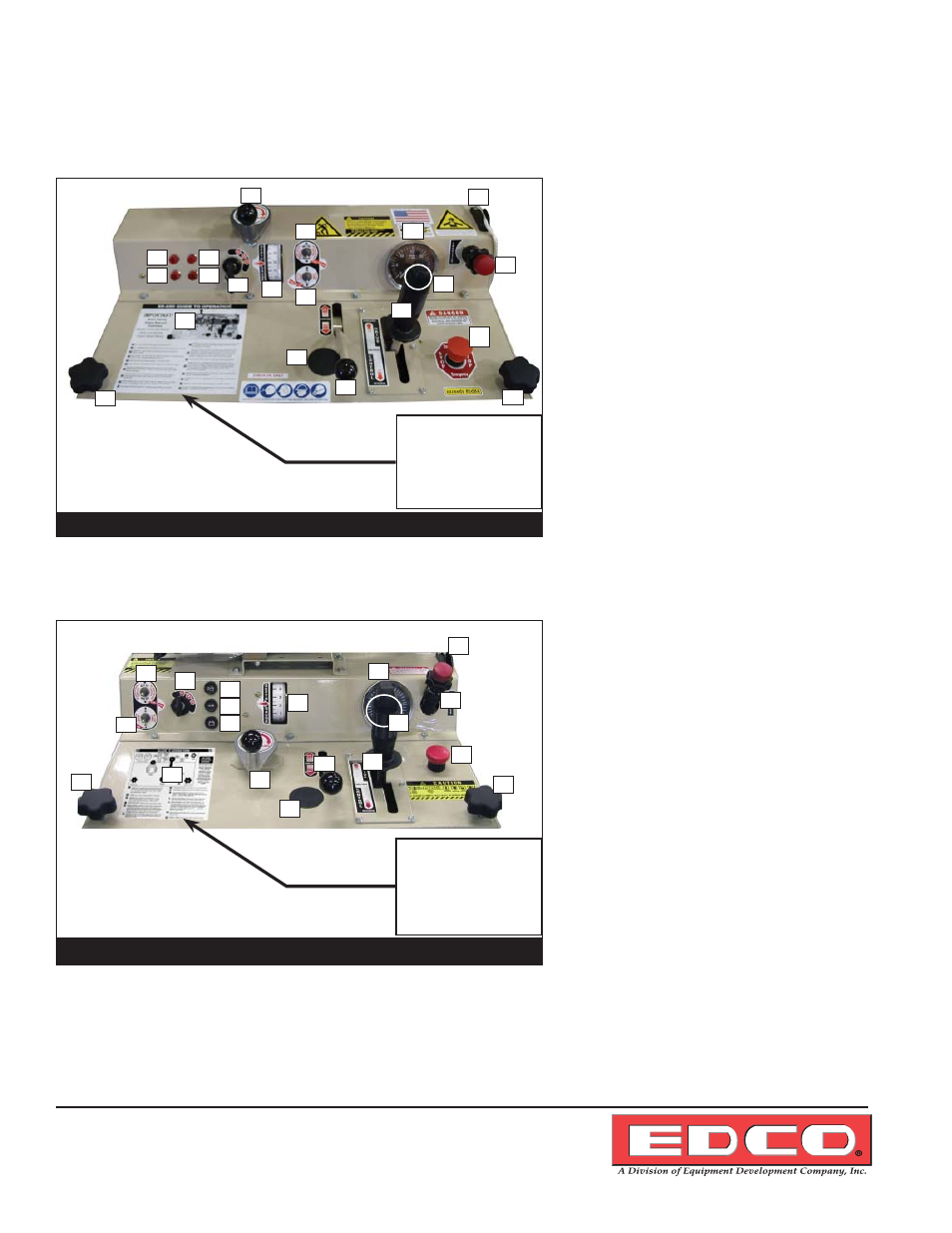
Diesel Powered Operating Controls
SS36-57D Operator’s Console
1. Oil Pressure Indicator
2. Oil
Temperature
Indicator
3. Alternator Failure Indicator
4. Glow Plug Indicator
5. Depth
Control
6. Ignition
Switch
7. Depth
Indicator
8. Blade Saver Switch
9. Water Pump Switch
10. Free Wheeling Clutch
11. Tachometer / Hour Meter
12. Blade Lift / Lower Rocker Switch
13. Drive Control Lever
14. Guide Bar Rope
15. Throttle
16. Emergency Stop Button
17. Hydraulic Oil Fill
18. Handle Locks
19. Guide To Operation
SS26-31D Operator’s Console
1. Oil Pressure Indicator
2. Oil
Temperature
Indicator
3. Alternator Failure Indicator
4. Depth
Control
5. Ignition
Switch
6. Depth
Indicator
7. Blade Saver Switch
8. Water Pump Switch
9. Free Wheeling Clutch
10. Tachometer / Hour Meter
11. Blade Lift / Lower Rocker Switch
12. Drive Control Lever
13. Guide Bar Rope
14. Throttle
15. Emergency Stop Button
16. Hydraulic Oil Fill
17. Handle Locks
18. Guide To Operation
NOTE: Due to design changes and advances in technology your machine may not look
exactly like machines illustrated in this manual. All controls function in the same manner.
Figure 5
1
2
5
6
4
3
11
7
8
9
13
10
12
15
14
16
17
17
18
DC Hydaulic
Power Unit mounted
inside compartment at
this location.
(See page 11)
(Figure 9)
Figure 4
1
17
2
5
3
6
7
8
14
13
11
12
16
15
9
10
18
18
19
DC Hydaulic
Power Unit mounted
inside compartment at
this location.
(See page 11)
(Figure 9)
4