Before starting the engine: *gasoline models only – EDCO CPM-10 User Manual
Page 6
E-CPL8-CPM-4-8-10-I-0112
Printed in USA
©2012
TVW
Page 6
100 Thomas Johnson Drive, Frederick, MD 21702-4600 USA
Phone (301) 663-1600 • 1-800-638-3326
Fax (301) 663-1607 • 1-800-447-3326
Website: www.edcoinc.com
Email: [email protected]
When using Hi-carbon steel or Tungsten Carbide cutter wheels:
IMPORTANT!
Read the engine manufacturer’s manual, familiarize yourself with engine start procedures.
3. Check level of oil in engine crankcase (engines are usually shipped dry, oil must
be added as per engine manufacturers instructions).
*
4. Check fuel level ( follow engine manufacturers instructions).
*
5. Be sure all guards (belt, motor, cutter wheel) are in place and secure.
6. Vacuum hose port should have hose attached or cap installed to control dust
generated during the cutting operation.
7. Locate engine on/off switch, if the engine is so equipped. On some engines the
throttle control is also the engine shut-off switch. Familiarize yourself with this
operation. *
8. All
EDCO gasoline engine operated planers are equipped with a STOP switch,
usually located on the handle. Use this switch for emergency engine shut-off.
*
9. Cold engine starting: Be sure fuel line valve is open. Set choke (separate lever
on some engines - others have choke as part of throttle control). Open throttle
(full to engage choke) 3/4 to full on engines with a separate choke. Turn engine
ignition switch ON. Be sure emergency STOP switch is ON.
*
10. Before starting determine that the recoil starter assembly turns freely, starter
rope pulls easily and the rope retracts properly.
*
BEFORE STARTING THE ENGINE: *Gasoline models only
Be sure that the cutter drum assembly has been properly installed and the cutter
drum shaft is in place and secured.
1. Select a level place at the job site. Set the “disengage lever” in the full DOWN
position. Refer to (Figure A).
It is most important to determine the position of the cutter wheels as they relate to
the slab or floor surface. If the drum assembly is filled with cutters, the cutter
wheels will most likely contact the slab when the “disengage lever” is lowered.
Refer to (Figure B).
Turn the “depth adjustment crank” UP until the cutter wheels are clear of the slab.
Refer to (Figure A). Follow these instructions each time before the engine is
started to prevent accidental damage to the slab.
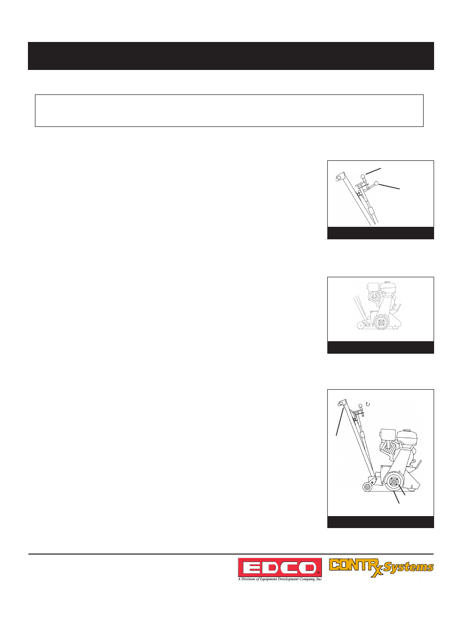
2. Raise the “disengage lever” to the full UP position. DO NOT force the lever. If
resistance is felt, turn the “depth adjustment crank” DOWN one or two turns.
This will allow the “disengage lever” to reach its normal full UP position. Refer to
(Figure C).
CPM-4-8-10-SACRALITE8 OPERATING INSTRUCTIONS
Figure B
Cutter Wheels Contacting Slab Surface
Figure A
Depth Adjustment Crank
Disengage Lever
Full DOWN
Position
Figure C
Cutters Clear of Slab
Surface
Cutter Drum
Cutter Wheel
Disengage
Lever
UP
Position
Depth Adjustment Crank
UP