Eagle Microsystems RA1000 User Manual
Page 5
5
I V .
INSTALLATION
A.
WALL PANEL MOUNTING
1.
Position the analyzer panel on a wall at eye level and as close as
possible to the sample source. Secure with bolts, leveling the
analyzer before securing.
B.
HYDRAULIC CONNECTIONS
1.
Connect the necessary length of drain hose to the drain outlet
on the analyzer. Secure with a hose clamp. Route hose to
maintain a gravity fed drain (downward slope).
2.
Connect one end of the 3/8” sample supply tubing to the source
using a suitable connection (customer supplied). Route tubing to
the sample filter chamber through the tubing holders on the
analyzer panel. Position the end of the tubing between the filter
0chamber and below the top of the overflow weir.
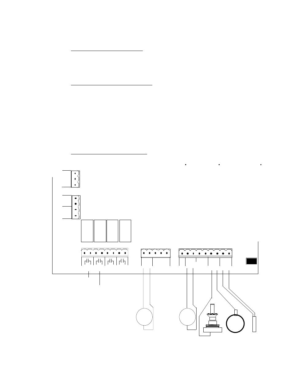
C.
TERMINAL CONNECTIONS
TB5
A B
1
Tx
5
+ -
4-20mA
1
9
+ -
+ -
+ -
+ -
CELL
THRM
+ -
PV1
+ -
PV2
4-20mA
+ -
+ -
mV
12V
COM
P01
SCR
PASS
Rx
2
SW
1
3
4
motor
TB4
K1
K2
K3
K4
2
AC
POWER
1
3
N
G
H
CONTROL
INPUT
+
-
CONTROL
OUTPUT
+
-
LOW
HIGH
RESIDUAL
RELAY
TB3
TB2
1
K1
K2
K3
K4
8
2 3 4
5 6
7
TB1