Set the control throws – Dynaflite DYFA3030 User Manual
Page 25
❏
5. Mount the wheels.
❏
6. Hinge the rudder, elevators and ailerons with the
heavy-duty hinges you have chosen.
❏
7. Mount the control horns onto the rudder,
elevator, and ailerons.
❏
8. Install the radio system. Our radio installation
consisted of the following:
A
.We used one hi-torque servo for each aileron.
B
. We used one hi-torque servo for each elevator,
with a separate pushrod for each.
C
.We used one hi-torque servo for the rudder.
D
.We used a standard servo for the throttle.
E
. We used a 1200 Mah battery pack to allow for
the additional servo drain.
❏
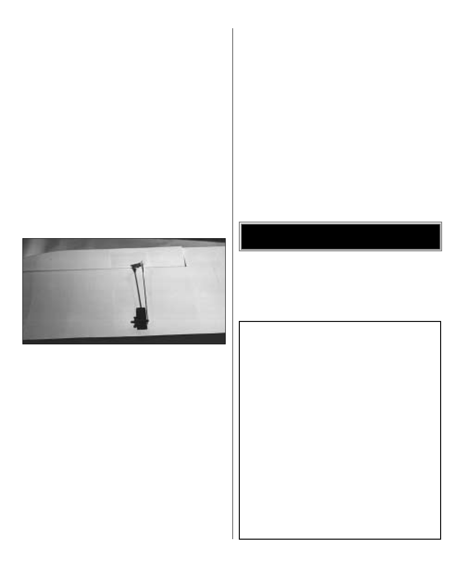
9. Install hi-torque aileron servos in the wing and
connect the linkages. We recommend the following
hardware for this purpose:
4-40 x 12" rod, threaded on one end (2)
4-40 threaded metal clevis (2)
4-40 lock nut (2)
Metal solder clevis (2)
❏
10. Fit and install the servos for the elevators and
rudder. Connect the linkages to the servos. If the
servos are mounted in the rear of the fuselage we
recommend the following hardware for this purpose:
4-40 x 12" rod, threaded on one end (3)
4-40 threaded metal clevis (3)
4-40 lock nut (3)
Metal solder clevis (3)
If the servos are mounted just aft of the firewall, you
will need a pushrod system 42" long. If the servos
are mounted at the TE of the wing, you will need a
pushrod system 28" long. In either case, Great
Planes solid wire pushrods or Accu-Glide
™
Nylon
Pushrods would work well.
❏
11. Install the throttle servo and connect the
linkage to the engine.
❏
12. Finish the cockpit. The cockpit area was
designed to be structure free so you can add as
much detail as desired. An optional cockpit kit is
available for this model and can be installed at any
time. Details in the cockpit area will really dress up
the appearance of your model.
Measure the throws at the widest part of the trailing
edge of the rudder, ailerons and elevators. After a
few flights you may change the throws to suit your
flying style.
We recommend the following control surface
throws:
HI
LOW
Elevator
1-1/16” Up
7/8” Up
1-1/16” Down
7/8” Down
Rudder
1-3/4” Left
1-1/2” Left
1-3/4” Right
1-1/2” Right
Ailerons
1-1/8” Up
13/16” Up
15/16” Down
11/16” Down
Throttle
: Set the throttle so that at “high stick” the
carburetor barrel is fully open and at “low stick”
with full to half throttle trim, the carburetor barrel
is nearly closed. At this position the engine should
run reliably at a low RPM (idle). To shut the
engine off, decrease the throttle trim tab.
SET THE CONTROL THROWS
25