Radio settings, Radio set-up – Dynaflite DYFA2018 User Manual
Page 22
arm. Trim the nylon pushrod 1/2" ahead of the
threaded rod.This will allow the threaded rod to
be securely attached. Remove the clevis from
the servo arm and thread the rod into the nylon
pushrod. Reattach the clevis to the servo arm.
0 9. Repeat steps 4 through 8 for the remaining
pushrod assembly.
Q 10. Once the pushrods are fully installed, use
the remaining 3/16" x 3/16" balsa to make
supports for the pushrod tubes. Place the
supports in the fuselage towards the leading
edge and trailing edge of the wing. The
supports will reduce the amount of flex in the
pushrods and result in more accurate inputs.
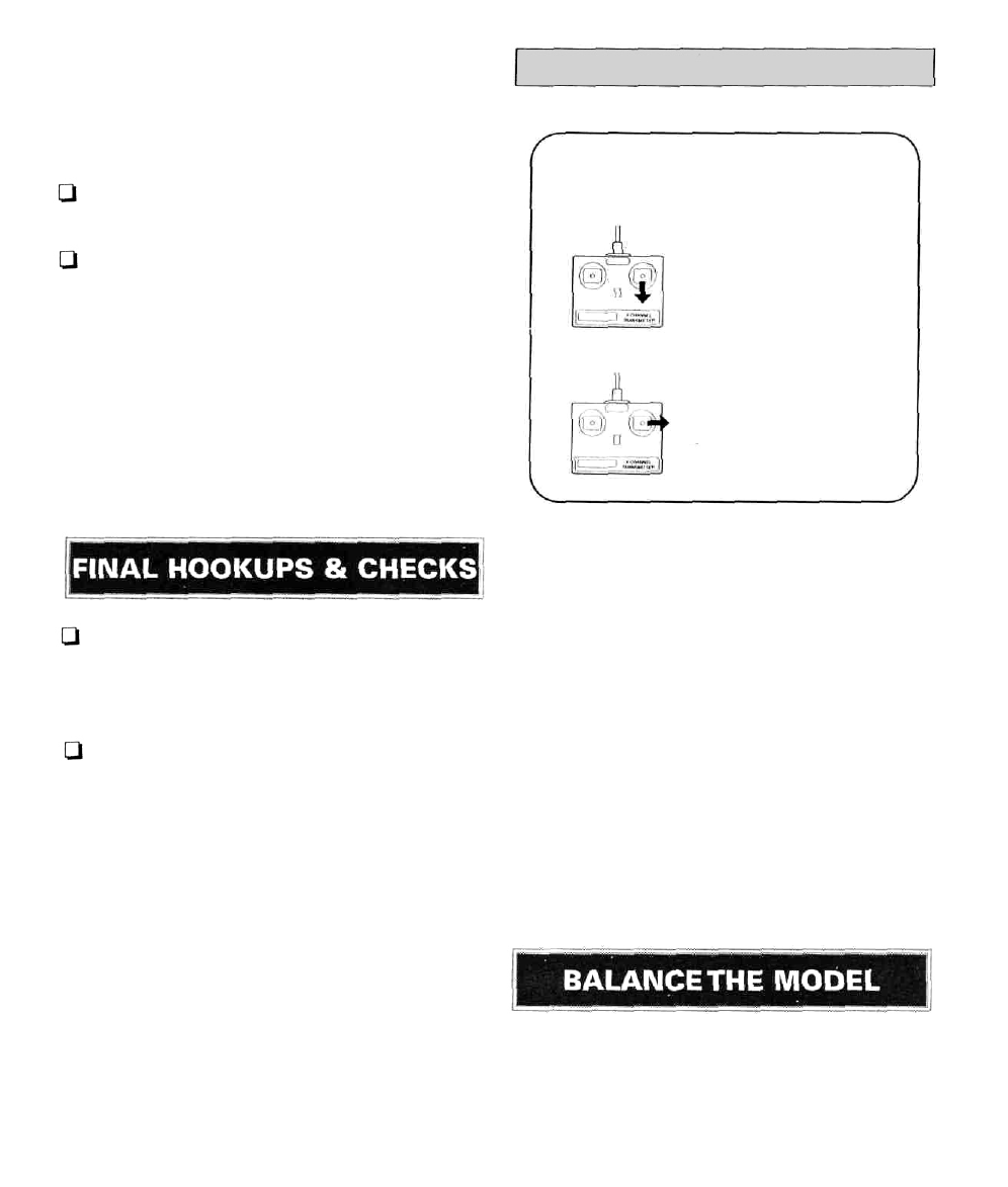
RADIO SETTINGS
RADIO SET-UP
ELEVATOR MOVES UP
RUDDER MOVES RIGHT
Use the sketch to make sure the control
surfaces are moving the correct directions.
The control throws are as follows:
Q 1. Drill a 1/8" hole in the bottom of the fuse as
shown on the plan for the tow hook attachment.
Install a 4-40 blind nut into the hole from the
inside of the fuselage.
Q 2. Attach the threaded tow hook to the
bottom of the fuselage by threading a 4-40 nut
and a 4-40 washer all the way onto the tow
hook and screwing the tow hook into the blind
nut. With the tow hook threaded almost all the
way into the blind nut, make sure the tow hook
is facing straight back and tighten the nut to
secure it.
A piece of self-adhesive foam rubber weather
stripping can be applied to the front of the
fuselage bottom to help protect it from getting
nicked during landings.
The canopy is held in place with a rubber band.
Use a medium-size rubber band to hold the
canopy in position as shown on the plan.
3/8" down
1-5/8" right
Elevator:
Rudder:
3/8" up
1-5/8" left
Note: This section is VERY important and
must not be omitted! A model that is not
properly balanced will be unstable and possibly
unflyable.
22