Diagram of components – Defibtech DDU-2450 Series Operating Guide User Manual
Page 4
DAC-E2530EN-BC
DAC-E2530EN-BC
6
7
For more detailed information, refer to the User Manual (on Defibtech User CD).
XX
XX
XX
RA
LA
LL
7
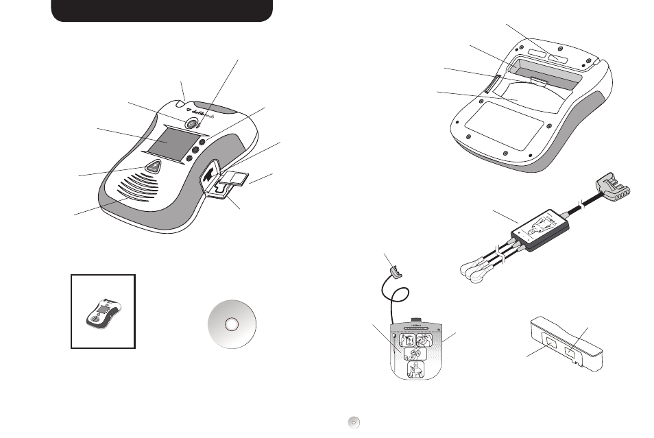
DIAGRAM OF COMPONENTS
OPERATING GUIDE
BOOKLET
Quick Reference
DEFIBTECH USER CD
Comprehensive User Manual
can be found on the CD
RA
LL
LA
RA
LA
LL
Active Status Indicator (ASI) –
Indicates the current status of the AED
Softkey Buttons
(Top, Center, Bottom) –
Buttons used to navigate
menus or select options
Pads Connector Socket –
Socket for pads connector
USB and Defibtech
Data Card (DDC Card)
Access Door – Access to the
USB connector port and
Defibtech Data Card slot
ON/OFF Button –
Turns AED on and off
Display Screen –
Displays video,
text prompts
and information
SHOCK Button –
Enabled/disabled by
software to allow the
user to discharge a
shock to the patient
Speaker
Defibtech
Data Card
(DDC Card)
(Optional)
ECG Monitoring Adapter
(Optional; DDU-2400/2450 only)
USB Port
DEFIBRILLATION
PADS PACKAGE
BATTERY PACK
BACK OF AED
Unit Serial Number
Battery Pack Opening
Battery Pack
Eject Release Latch
Pad Storage Area
Pads Connector
Defibrillation
Pads
Defibrillation Pads
Expiration Date
(on back of package)
Battery Pack
Serial Number
Battery Pack
Expiration Date
FRONT OF AED
Defibtech DDU-2000 Series
Automated External Defibrillator
• DDU-2300
• DDU-2400
• DDU-2450
Operating Guide