Rear panel description – D.A.S. Audio SLA Series User Manual
Page 20
4
G)
LED
Standby
The standby LED (white) illuminates when
current overloading is detected by the power
supply. At that moment the main power supply
voltage, that feeds the amplifying stage channels,
gets disconnected. The secondary voltage supply
will still be on, and will turn off only when the
mains power cord gets unplugged and/or the
amplifier is switched off (See Switch On/Off
section).
H) Cooling air outlet grilles
Fan cooling permits airflow through the most
vital parts of the amplifier. Since the airflow finds its
way out through these grilles, keep them as clean
and dust-free as possible to assure proper cooling.
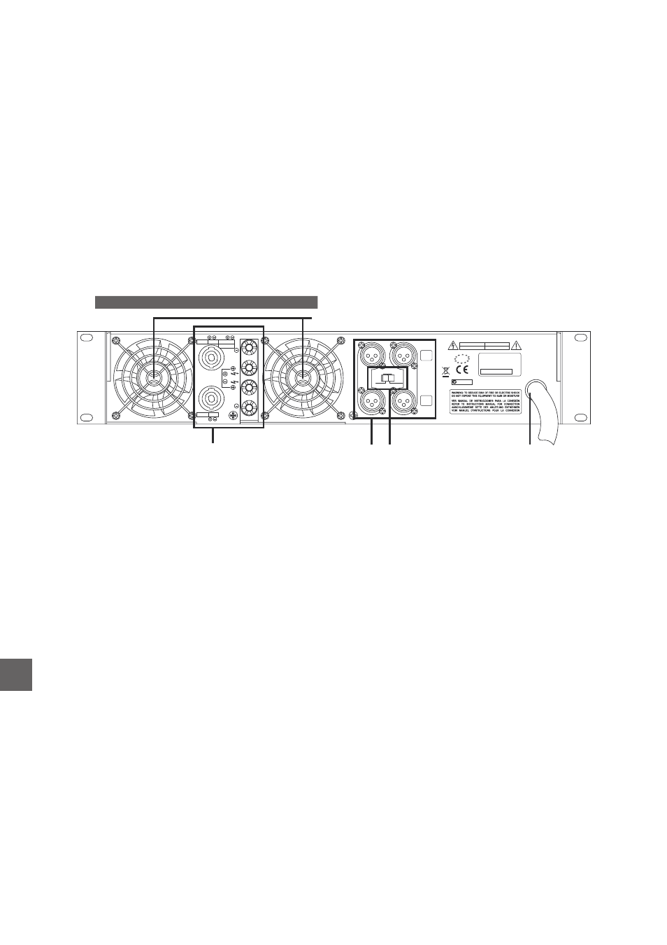
A) Output connections
For connection of channel outputs to speakers,
both binding posts and Speakon NL4 connections
are provided.
For the binding posts, polarity is clearly
indicated by black (–) and red (+) output terminals.
For the Speakon situated on the right, pin
assignments are:
Channel A : +1 / -1.
Channel B : +2 / -2.
Bridge : +1 / +2.
For the Speakon situated on the left, pin
assignments are:
Channel B : +1 / -1.
Thus
you
may choose
to
connect
both
channels using only one or the two Speakon
connectors, depending on your needs.
B) Inputs
An XLR input is connected in parallel to an XLR
output.
Nominal input impedance is 20k ohm for
balanced use and 10k ohm for unbalanced use.
Polarity
complies
with
AES14-1992
(ANSI
S4.48-1992) and therefore pin assignments are:
1 = GND (Ground).
2 = (+) non-inverted signal.
3 = (–) inverted signal.
C) Input mode
D) Mains lead
The mains lead is terminated on a plug that will
change according to the amplifier’s mains voltage
and area location. If you need to cut off the plug to
replace it for the type used in your region, cable
colour codes are brown (live), blue (neutral) and
yellow-green (earth).
E) Fan inlet grilles
Like for the front outlet grilles, keep clean and
dust-free to assure free air intake for proper
cooling.
REAR PANEL DESCRIPTION
CH
B
CH
A
BRIDGE
BRIDGE 1+ 2+
CH A
CH B
1+
2+
1-
2-
CH B
1+ 1-
SPEAKER
OUTPUT
SIGNAL
INPUT
SIGNAL
OUTPUT
D.A.S. AUDIO S.A. (Valencia) SPAIN
Serial Number:
EUROPEAN
PRODUCT
N1918
MADE IN SPAIN
CAUTION
ATTENTION
RISK OF ELECTRIC SHOCK
DO NOT OPEN
DANGER D’ELECTROCUTION
NE PAS OUVRIR
STEREO
BRIDGE
PARALLEL
CH B
,
CH A
BRIDGE
OR
PARALLEL
A
B
C
D
E
This switch allows the selection for the input
configuration mode: stereo, parallel or bridge.
Typically the amplifiers are used in stereo
mode, where the input to channel A feeds channel
A and the input to channel B feeds channel B.
Parallel mode allows feeding both channels
with the signal plugged into channel A. Channel
B's input is disconnected in this mode.
Bridge mode allows easy wiring of an amplifier
in mono mode. The input to channel A feeds both
channels with appropriate polarity. Refer to the
“Bridge Mode Operation”.
Appendix for further information.
EN
Manual del Usuario
/ SLA / User’s Manual