D.A.S. Audio SLA Series User Manual
Page 19
3
INTRODUCTION
General
Thank you for purchasing a D.A.S. power
amplifier. It has been built with the most advanced
modular technology, and has been designed
through the use of computer-aided design for both
the electronic and mechanical parts.
Features
?
?
?
?
?
?
?
?
?
?
?
?
?
Class H.
Switching Mode Power Supply.
Dual balanced XLR inputs.
Binding post and Speakon output connections.
Variable speed back-to-front fan cooling.
Front located volume controls.
Complete and independent protections on
each
channel
against
output
short-circuits,
overloading and overheating.
The power supply is protected against short-
circuits, voltage and current overloading; triggering
the latter the standby mode.
Overload,
short-circuit,
DC
and
thermal
protection.
Each channel has separate circuitry, built onto
a separate power module, facilitating servicing in
the event of a breakdown.
Stereo, parallel and mono operation modes.
Clip limiters.
Clip, protection and idle LED indicators.
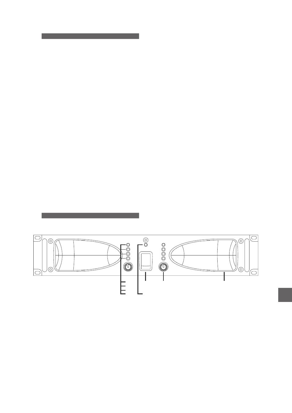
FRONT PANEL DESCRIPTION
A) Power switch
Turns the amplifier on ("|" position"). The power
switch is of the magnetothermic type, so it
switches to off ("0" position) automatically when
input current overloading protection triggers.
B)
LED
Power
When these blue LEDs lit, it shows that both
amplifier channels are ready.
C) Input
controls
Level
Volume
levels
for
each
channel
can
be
adjusted by using the knobs found on the front
panel. The effect is the same as adjusting the gain
of the amplifier. Gain is maximum when the level
rotary potentiometer is rotated fully clockwise.
D)
LED
Clip
In the event that the signal’s excursion exceeds
the maximum voltage from the power supply, the
unit will indicate saturation through the clip LED of
the channel involved.
E)
LED
Protection
When a channel's output is disconnected by
the amplifier's protection, this white LED is on. A
channel’s protection may be triggered by:
?
?
?
Overheating sensed at any part of a
channel. When the amplifier has cooled down,
the channel’s output will be connected and
operation will resume. The control circuit has
some degree of built-in hysterisis to avoid turn-
on and off oscillations.
Presence of DC at a channel’s output.
Since it may severely damage speakers, the
amplifier will deactivate the output in the event
that DC levels are too high. If load impedance
is too low, the amplifier is also deactivated.
Once DC is no longer present, the
LED will turn off and output is reactivated.
Short-circuit
at
a
channel’s
output.
Although this protection is provided, it is
dangerous that the amplifier remains in this
situation for a long time. In case of a short-
circuit, turn off the amplifier while examining
any equipment connected to the amplifier’s
output, together with the connections and
cabling. In this case, once the short circuit is
gone the output is NOT reactivated, but the
amplifier needs to be switched off and on.
Protection
?
When the amplifier is switched on, the
output is also deactivated for a few seconds to
prevent dangerous transients from damaging
the speakers, and the
LED is on
until the amplifier is ready for use.
Protection
F)
LED
Signal
These blue LEDs show the presence of signal
at the amplifier's inputs, and is dependent on the
position of the level control.
PROFESSIONAL POWER AMPLIFIER
Protection
Protection
Clip
Clip
On
On
Signal
Signal
CH A
CH B
Standby
®
A
B
C
D
E
F
G
H
EN
Manual del Usuario
/ SLA / User’s Manual