Comtrol RA Series User Manual
Rocketport, And rocketport, Series setting the dip switch reference
Setting the
DIP
Switch
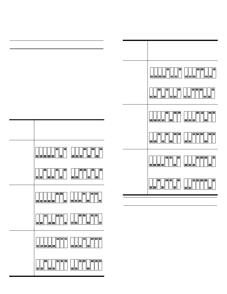
The following table is provided for you in cases where
you did not receive device driver documentation or for
your reference. The device driver documentation
provides controller installation procedures and advises
you how to set the
DIP
switch.
To prepare your controller for installation, you may
need to set the
I/O
address
DIP
switch. The default
I/O
address range is 180 through 1C3.
For the first controller, select a 68-byte
I/O
address
range. For subsequent controllers, select a 64-byte
range.
RocketPort controllers use
I/O
address ranges at 400
hexadecimal (hex) intervals above the
I/O
range. Most
peripherals use
I/O
address ranges between 0 and 3FF
hex. If you have peripherals installed above 400h, you
may experience an
I/O
conflict. The first controller
determines the settings for additional controllers.
Installing the Controller
After you set the
I/O DIP
switch, you are ready to
install the controller. Use the following steps to install
the controller:
1.
Turn the power switch for the system unit to the
OFF
position.
2.
Remove the system unit cover.
3.
Select a slot to install the controller.
4.
Remove the expansion slot cover.
5.
Insert the controller in the expansion slot, make
sure that it is properly seated.
6.
Attach the controller to the chassis with the
expansion slot screw.
7.
Replace the cover on the system unit.
Controller
#1 I/O
Address
Range
DIP
Switch Settings
(Controller #1 determines the other
controller settings.)
100 - 143 hex
140 - 183 hex
180 - 1C3 hex
(Default)
Controller #1
Controller #2
ON
1
2
3
4
5
6
7
8
ON
1
2
3
4
5
6
7
8
ON
1
2
3
4
5
6
7
8
ON
1
2
3
4
5
6
7
8
Controller #3
Controller #4
Controller #1
Controller #2
ON
1
2
3
4
5
6
7
8
ON
1
2
3
4
5
6
7
8
Controller #3
Controller #4
ON
1
2
3
4
5
6
7
8
ON
1
2
3
4
5
6
7
8
Controller #1
Controller #2
ON
1
2
3
4
5
6
7
8
ON
1
2
3
4
5
6
7
8
ON
1
2
3
4
5
6
7
8
ON
1
2
3
4
5
6
7
8
Controller #3
Controller #4
200 - 243 hex
280 - 2C3 hex
300 - 343 hex
Controller
#1 I/O
Address
Range
DIP
Switch Settings
(Controller #1 determines the other
controller settings.)
Controller #1
Controller #2
ON
1
2
3
4
5
6
7
8
ON
1
2
3
4
5
6
7
8
ON
1
2
3
4
5
6
7
8
ON
1
2
3
4
5
6
7
8
Controller #3
Controller #4
Controller #1
Controller #2
ON
1
2
3
4
5
6
7
8
ON
1
2
3
4
5
6
7
8
ON
1
2
3
4
5
6
7
8
ON
1
2
3
4
5
6
7
8
Controller #3
Controller #4
Controller #1
Controller #2
ON
1
2
3
4
5
6
7
8
ON
1
2
3
4
5
6
7
8
ON
1
2
3
4
5
6
7
8
ON
1
2
3
4
5
6
7
8
Controller #3
Controller #4
RocketPort
®
and RocketPort
RA
Series
Setting the DIP Switch Reference
Document Outline
- 1. Turn the power switch for the system unit to th...
- 2. Remove the system unit cover.
- 3. Select a slot to install the controller.
- 4. Remove the expansion slot cover.
- 5. Insert the controller in the expansion slot, ma...
- 6. Attach the controller to the chassis with the e...
- 7. Replace the cover on the system unit.
- a. Attach the male end of the RocketPort or Rocket...
- a. Attach the male end of the Octacable to the con...