Installation – Clippasafe 120 Pressure Fit Gate User Manual
Page 3
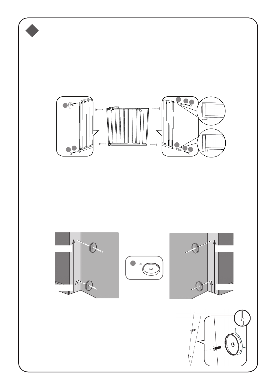
1
Installation
On the latch side of the gate, insert 1 screw adjuster ‘A’ with nut ‘B’ into
the holes provided on the bottom of the gate. Screw 1 screw adjuster ‘A’
into the hole provided next to the handle. On the other side of the gate
insert 2 casings ‘C’ followed by 2 screw adjusters ‘A’ with nuts ‘B’ into the
holes provided. Be sure to insert both casings ‘C’ with the notch
facing downwards.
Mark the position for the wall fixings ‘D’ on the wall surface you wish the
gate to hinge from. The hole for the lower wall fixing should be 26.5mm
from the floor. The hole for the upper wall fixing should be 721.5mm from
the floor. On the other side of the opening mark the position for the wall
fixings ‘D’. This should be the side you want the gate to open from. The
hole for the lower wall fixing should be 26.5mm from the floor. The hole
for the upper wall fixing should be 724mm from the floor.
Fix the wall fixings ‘D’ using the appropriate
fixings depending on the surface available:
wood screws for wooden surfaces, multi-use
dowel and concrete screws for concrete
surfaces, multi-use dowel and cement screws
for cement surfaces, metal screws for metal
surfaces. These screws are not provided.
2
A
C
B
A
C
B
A
B
A
26.5mm
721.5mm
4
D
26.5mm
724mm