System configuration, T2e cpu unit configuration, T2e basic components – Toshiba T2E User Manual
Page 4
Attention! The text in this document has been recognized automatically. To view the original document, you can use the "Original mode".
System Configuration
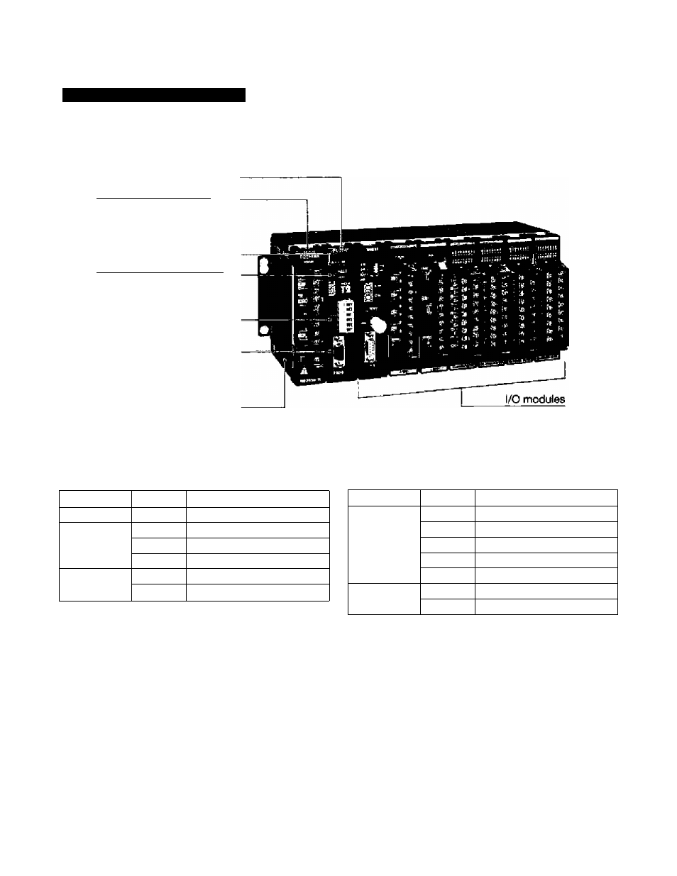
T2E CPU Unit Configuration
CPU module
Power supply module
CPU status indicators
Operation nKJde switch
Optional communicatliMi port
(Add-on option card,
RS-2^C or RS-4S5)_______
Programmer port (RS-232C)
Rack
T2E basic components
item
Type
Description
CPU module
PU234E
9.5 k steps, clock/calendar
CPU add-on
option card
CM231E
RS-48S port, w/ battery
CM232E
RS-232C port, w/ battery
BT231E
Battery card
Power supply
module
PS261
100 to 240 Vac
PS31
24 Vdc
Item
Type
Description
CPU rack
BU218
8 irO slots, expandable
UBB2
7 I/O slots, expandaUe
UBBl
4 I/O slots, expandable
UBA2
7 I/O ^ots, non expandable
UBAI
4 I/O slots, non ej^ndable
Expansion
rack
BU2E8
8 I/O slots
BU2&6
6 I/O slots
• The CM231E and the CM232E are optional communicatlcMi cards for T2E. These cards also have the optional
battery mounted on them.
• The CM231E has a terminal block for RS-435 interface. The CM232E has a D-Sub 9-pin (female) connector for
RS-232C interface.
• The BT231E is a card that has only the optional battery.
• The T2E CPU module can hold only one option card: CM231E, CM232E or BT231E.
• The UBA1 and the U8A2 are stand-alone CPU racks, expansion racks can not be connected.
• The UBBl and the UBB2 can be used as either CPU or expansion racks. When the UBB1 or UBB2 is used as
expansion rack, only one expulsion rack can be connected.
• The BU266 and the 6U268 can be used as either CPU or expansion racks. When the BU2B6 is used as CPU
rack, (t has 5 I/O slots. When the BU268 is used as CPU rack, it has 7 I/O slots.