Temperatu re- pressure relief valve, A warning, Warning ‘relief valve opening – Kenmore POWER MISER 153.32676 User Manual
Page 9: Temperature-pressure relief valve, Installation instructions (cont’d)
Attention! The text in this document has been recognized automatically. To view the original document, you can use the "Original mode".
Installation Instructions (cont’d)
Temperatu re- Pressure
Relief Valve
A WARNING
At the time of manufacture this water heater was provided
with a combination temperature-pressures relief valve cer~
tified by a nationally recognized testing laboratory that
maintains periodic inspection of production of listed equip
ment or materials, as meeting the requirements for Relief
Valves and Automatic Gas Shutoff Devices for Hot Water
Supply Systems, and the current edition of ANSI Z21.22 •
CSA
4.4
and the code requirements of ASME. If replaced,
the valve must meet the requirements of local codes, but
not less than a combination temperature and pressure
relief valve certified as meeting the requirements for Relief
Valves and Automatic Gas Shutoff Devices for Hot Water
Supply Systems, ANSI Z2I.22 • CSA 4.4 by a nationally rec
ognized testing laboratory that maintains periodic inspec
tion of production of listed equipment or materials.
The valve must be marked with a maximum set pressure
not to exceed the marked hydrostatic working pressure of
the water heater (ISO lbs. p.s.i.) and a discharge capacity
not less than the water heater input rate as shown on the
model rating plate. (Electric heaters - watts divided by 1000
X 3412 equal BTU/Hr. rate.)
Your local jurisdictional authority, while mandating the use
of a temperature-pressure relief valve complying with ANSI
Z2I.22 • CSA 4.4 and ASME, may require a valve model dif
ferent from the one furnished with the water heater.
Compliance with such local requirements must be satisfied
by the installer or end user of the water heater with a local
ly prescribed temperature-pressure relief valve installed in
the designated opening in the water heater in place of the
factory furnished valve.
For safe operation of the water heater, the relief valve must
not be removed from it's designated opening or plugged.
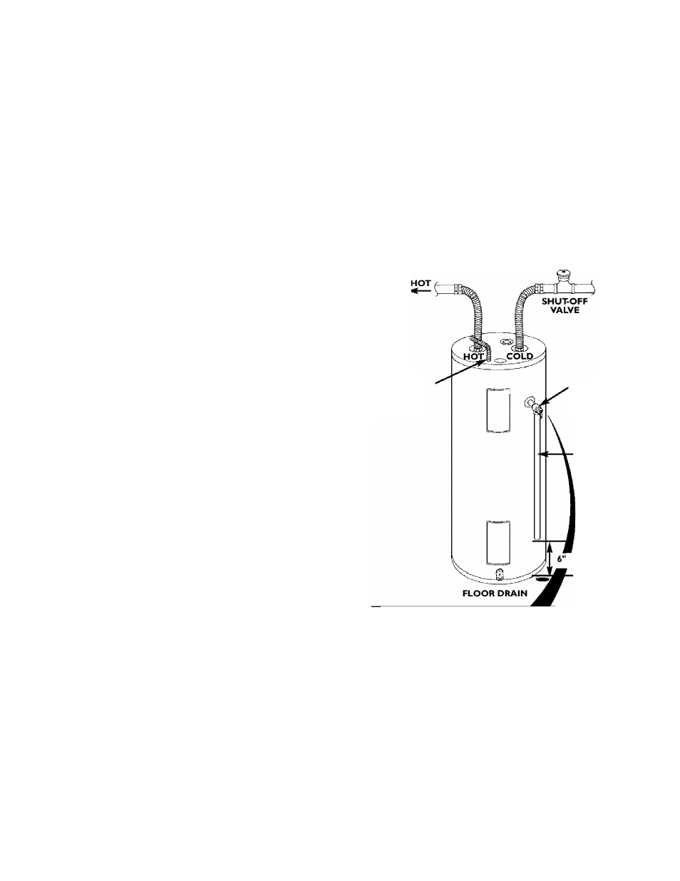
The temperature-pressure relief valve must be installed
directly into the fitting of the water heater designated for
the relief valve. Position the valve downward and provide
tubing so that any discharge will exit only within 6 inches
above, or at any distance below the structural floor. Be cer
tain that no contact is made with any live electrical part.
The discharge opening must not be blocked or reduced in
size under any circumstances. Excessive length, over 30
feet, or use of more than four elbows can cause restriction
and reduce the discharge edacity of the valve.
No valve or other obstruction is to be placed between the
relief valve and the tank. Do not connect tubing directly to
discharge drain unless a 6" air gap is provided. To prevent
bodily injury, hazard to life, or property damage, the relief
valve must be allowed to discharge water in quantities
should circumstances demand. If the discharge pipe is not
connected to a drain or other suitable means, the water
flow may cause property damage.
The Discharge Pipe:
•
Must not be smaller in size than the outlet pipe size of
the valve, or have any reducing couplings or other
restriction.
• Must not be plugged or blocked.
• Must be of material listed for hot water distribution.
•
Must be installed so as to allow complete drainage of
both the temperature-pressure relief valve, and the dis
charge pipe.
• Must terminate at an adequate drain.
• Must not have any valve between the relief valve and tank.
A WARNING
The temperature-pressure relief valve must be manually
operated at least once a year. Caution should be taken to
ensure that (I) no one is in front of or around the outlet
of the temperature-pressure relief valve discharge line,
and (2) the water manually discharged will not cause any
bodily injury or property damage because the water may
be extremely hot.
If after manually operating the valve, it fails to complete
ly reset and continues to release water, immediately,
close the cold water inlet to the water heater, follow the
draining instructions, and replace the temperature-pres
sure relief valve with a new one.
CONDUIT
COLD
■TEMPÊRATURÊ-
PRESSURE
RELIEF VALVE
DISCHARGE PIPE
(Do not cap or plug)
AIR GAP
WARNING ‘RELIEF VALVE OPENING’
This widor is prowidad wifis a ciHr^birtation Tanperalura^fassure Relisf S$led as corr^pg w^h
Bsa ^artdard for Relef V^vas and iijtomattc Gas SsutoS Devices for
Net
Watw Sysims,
ANS
.22
and the code rec^uir^ents of
ASME-
Your locaMurisiSKion^ authority, white mandating the use of a Tempwalufe-PEes&ira Reltì Vedve complyirtg
with WfS Z2l.22and ASME, may raipra avaKie medai diarertlfrom fise one furnished with the water heater,
CompSance wifis such loc^ requirements must be safi^ted by fiia insta^^ or end user of the w^ar heater with
a loccdly prescribed TemperaPre-Pressure Reli^ Valve instiled in the deagrtaled opening irt the water
heeler.
“Afs-< '
' ,MC-
BRASS
"}UPLlNG
TANK
PiTfiMi'-;
T&P RÊÜÊF
VALVE PROSE
MUST EXTEND
INTO TANK
I
TEMPERATURE-
LPRESSURE
f RELIEF VALVE
SlVû" X /. )
BRAbb ГЙ
NIPPLE
Щ T&P
SHANK
r.LENGTH
• if a short shank {less than
2") temperature-pressure relief vah/e is to be instaited
(as shown), a nippie and coupling must be used.
♦ if a tong shank {
2’ or longer) is to be instalted, do not use tfie nippie and coupling.
irtstali Tarr|>eratyre'Pres^re protective equipment required by tecíü codes, but not less thai a combina
tion Temperature-Pressure Relief Valve certified as meeting the requirements for Relief Vaives and
Automatic Gas Shutoff Dewcestor HM-Water Supply Syst^s, WfS Z
21.22 by a n^tonally recognised test
ing juratory that manlains pehodc inspection of produclicHt ol li^ed equ^m^l or rrtat^i^s. The víüve
must be Drilled, provided with kiNng, or otherwise insl^ied so that discharge can exit only within
6 inches
cèove, OT at aiy distance b^ow the stmeurrai floor, and cannot contact any IMe eiectneal part,"
For safe operation of the w^er heater, the Relief Valve must nol be removed or plugged.
See manual heading - Temperature-Pressure Relief Valve" for instailafion and míünlenance ol Rellet
Valve, iSscharge pipe and other safely precautions.