Kenmore 3405602 User Manual
Page 14
Attention! The text in this document has been recognized automatically. To view the original document, you can use the "Original mode".
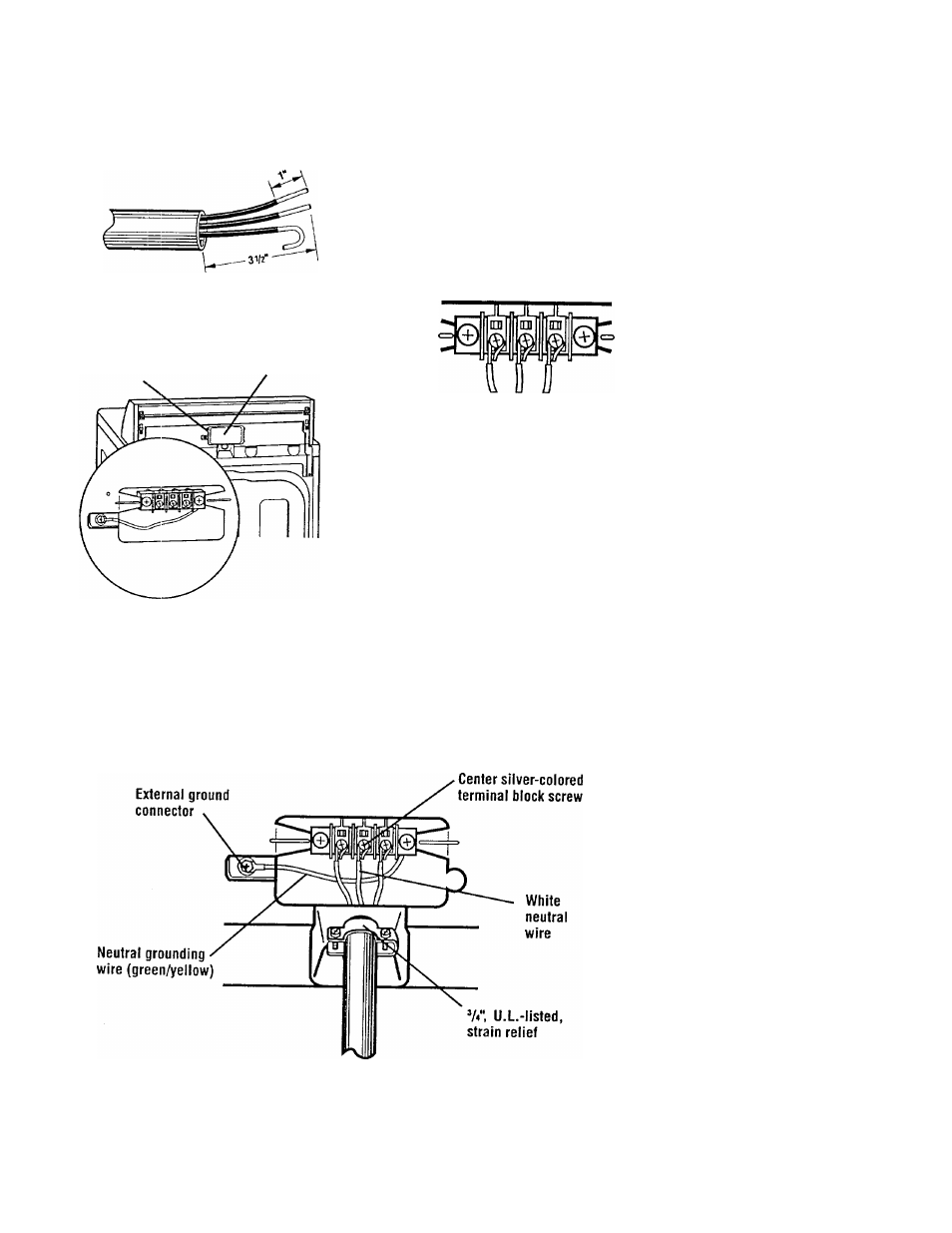
STEP 1b. Cut 1 inch of insulation from
the end of each insulated wire. Shape
the end of each wire into a “U” shaped
hook.
STEP 2.
Remove hold-down screw and
terminal block cover.
Hold-down screw
Terminal block cover
STEP 3. Attach a %-inch, U.L.-listed,
strain relief to the hole below terminal
block opening. Strain relief should have
a tight fit with dryer cabinet and be in a
horizontal position. Put the direct wire
cable through the strain relief.
STEP 4. Loosen or remove terminal block
screws. Connect the neutral wire (white
or center) of direct wire cable under the
center screw of the terminal block.
STEP 4a. Place the hook-shaped end
of the wire over the terminal block screw.
The open side of the hook should face
to the right. Squeeze hook end of wire
together to form a loop.
STEP 5.
Connect the other two wires
to outer terminal block screws using the
same method(s) described in STEP 4a.
Tighten all terminal block screws firmly.
STEP
6. Tighten the strain relief screws.
STEP 7.
Insert tab of terminal block
cover into slot of the dryer rear panel.
Secure cover with hold-down screw.
If local codes do not permit the
connection of a frame-grounding
conductor to the neutral wire, see
the instructions on page 15.
Otherwise, proceed with Exhaust
Installation. See “CONNECT
EXHAUST” on page 19.
3-Wire Connection with Direct Wire
and Frame-Grounding Conductor
14