Engine installation – Carl Goldberg GBGA1047 User Manual
Page 13
13
ENGINE
INSTALLATION
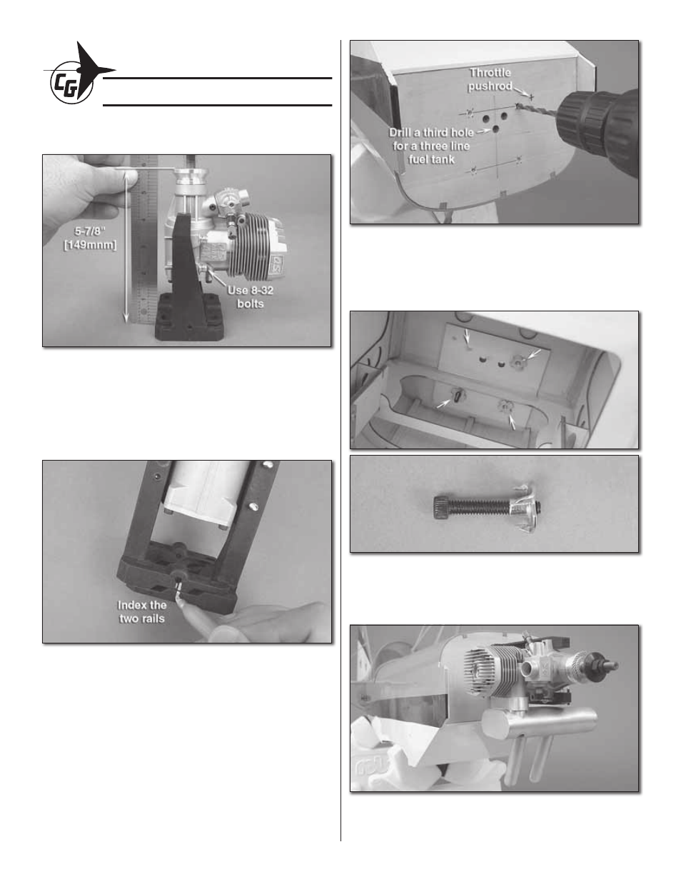
FIT THE ENGINE
❏
1. Fit the engine to your engine mount so that the drive
washer of the engine is 5-7/8" [149mm] from the base of the
mount (fi rewall). Use a minimum of 8-32 bolts to attach the
engine to the mount (these are not supplied with the kit). Drill
and tap your mount.
❏
2. Make index marks between the two sliding rails. This
will help you note the position of the rails for the next step.
❏
3. Remove the engine from the mount, keeping the two
sides of the mount together.
❏
4. Center the engine mount over the cross-hairs etched
into the fi rewall. Be careful to note the position of the mount
so that the cylinder head is oriented on the proper side of the
fuselage. Mark the location for the engine mount bolts and
where you will need to drill the hole for the throttle pushrod.
❏
5. Drill four 7/32" [5.6mm] holes for the engine mount
bolts. Drill a 5/32" [4mm] hole for the throttle pushrod while
you’re at it. If you’re going to use a three line fuel tank setup,
go ahead and drill a third hole now. Use a 7/32" [5.6mm] drill
bit for this.
❏
6. Locate the four (4) 8-32 x 1" [25mm] engine mount bolts
and their associated 8-32 blind nuts. Press the blind nuts into
the back side of the fi rewall. You can use the bolts to help you
pull the blind nuts into position.
❏
7. Bolt the engine and the engine mount to the fi rewall.
Temporarily attach the muffl er.
13