Carl Goldberg GBGA1047 User Manual
Page 12
12
❏
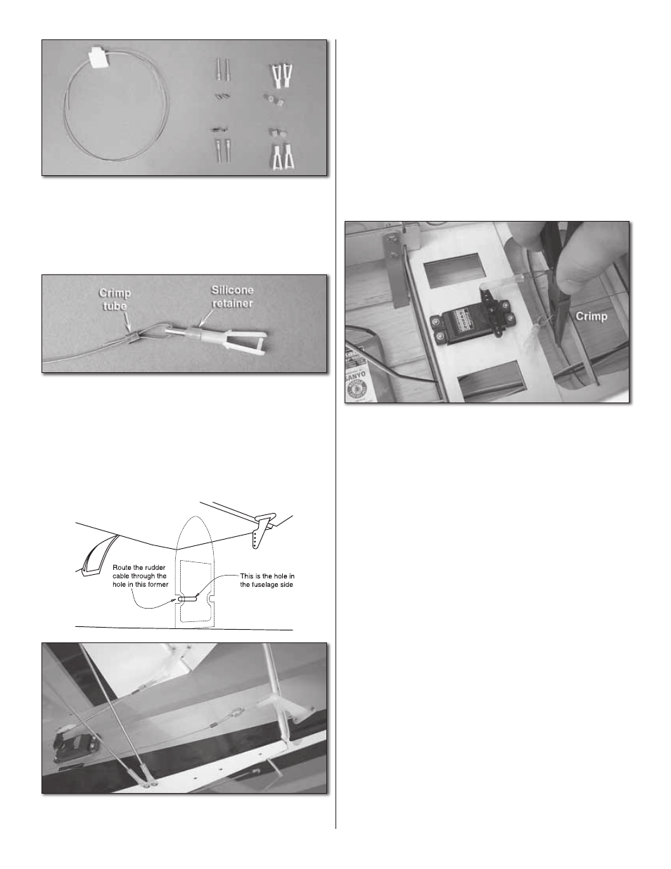
6. Locate two (2) 36" [915mm] control cables, four (4) threaded
cable couplers, four (4) crimp tubes, and four (4) clevises.
❏
7. Thread a clevis onto each of the four threaded cable
couplers. Thread it on far enough so that the coupler threads
are 1/16" [1.6mm] past the barrel of the clevis.
❏
8. Prepare one end of each cable as shown. Fold at least
1" [25mm] of cable over and crimp it tightly using your pliers.
DO NOT crimp the other end of the cable yet. You will need
to custom fi t it later.
❏
9. Visually inspect the crimps that you just made. Check
to see that the wires are fi rmly crimped in place. Inspect any
further crimps that you must make in the same manner
❏
10. Attach a control cable to the outermost hole of one
rudder control horn and route it into the fuselage. There is a
former directly ahead of the cable exit holes. Be sure to route
the cable through the hole in the former.
❏
11. Visually inspect the cable routing. Make sure that your
rudder cables will not interfere or become tangled in the
elevator servo leads.
❏
12. Tape a straightedge to the side of the fi n and rudder to
hold the rudder straight.
❏
13. Center your rudder servo. Note: It may be helpful to
leave your radio “ON” during the rigging procedure to ensure
that the rudder servo will remain straight.
❏ ❏
14. Extend the other end of the rudder cable into the
fuselage. Assemble the cable couplers and adjust the length
of the rudder cable as close as you can. Crimp the cable.
Don’t worry too much about getting the cable length perfect.
You can still adjust the cables using the threaded clevises.
❏
15. Repeat the last step for the other cable.