Carl Goldberg GPMA1966 Tiger 2 ARF User Manual
Page 16
16
3. Use a 4x20mm machine screw, engine mount half, and
a 4mm fl at washer to draw the four 4mm blind nuts tight into
the engine mounting holes. Confi rm that the holes you are
using line up with the holes in the engine mount halves (the
unused holes are for a brushless motor mount). Install the
motor mount halves using four 4x20mm machine screws,
four 4mm fl at washers, and thread locking compound.
4. Cut a piece of 1/4" [6mm] foam rubber (not included)
to fi t the fuel tank. Lay the foam rubber inside the fuel tank
compartment. Fit the fuel tank into the compartment and pull
the fuel tank neck through the hole in the fi rewall. Install the
stopper into the tank (be sure the correct side is facing up).
Do not over-tighten the stopper screw.
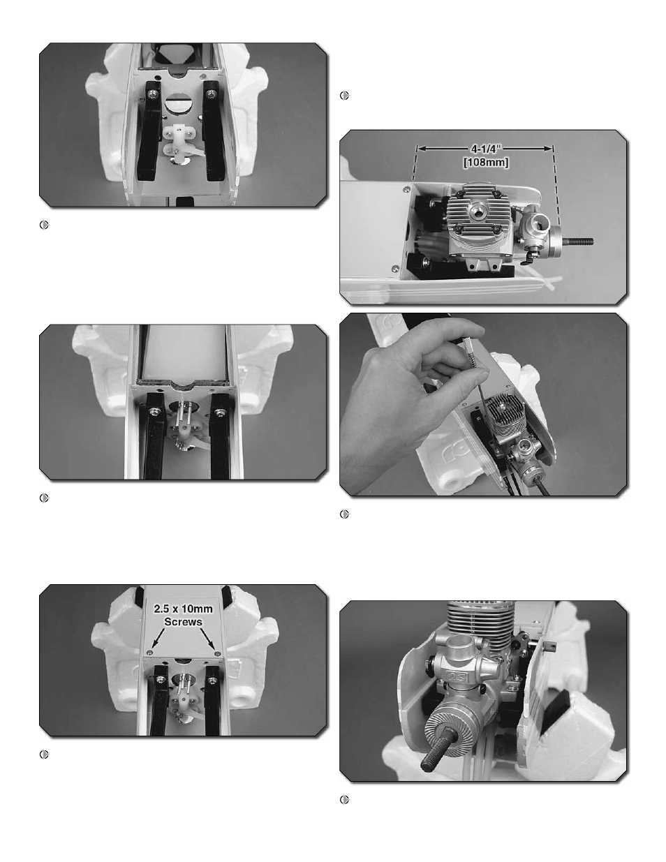
5. Line the top and sides of the tank with additional foam
rubber. The tank should be held securely by the foam rubber.
Fit the fuel tank hatch cover in place and drill two 1/16" [1.6mm]
pilot holes through the forward end of the hatch cover and into
the fi rewall. Thread a 2.5x10mm washer head self-tapping
screw into each hole and back it out. Apply a drop of thin CA
to each hole to harden the wood. Install the hatch cover using
two 2.5x10mm washer head self-tapping screws.
6. Attach a 6" [152mm] piece of fuel tubing to each of the
tubes in the fuel tank stopper.
7. Position your engine 4-1/4" [108mm] from the fi rewall.
Use a Great Planes Dead Center Hole Locator to mark the
location of the engine mount holes onto the engine mount
halves. If necessary, carve away any portion of the fuselage
that interferes with the needle valve or exhaust. Drill 1/8"
[3.2mm] holes through the marks you made.
8. Attach the engine to the engine mount halves using four
3x25mm machine screws, eight 3mm fl at washers, and four