Carl Goldberg GPMA1966 Tiger 2 ARF User Manual
Page 10
10
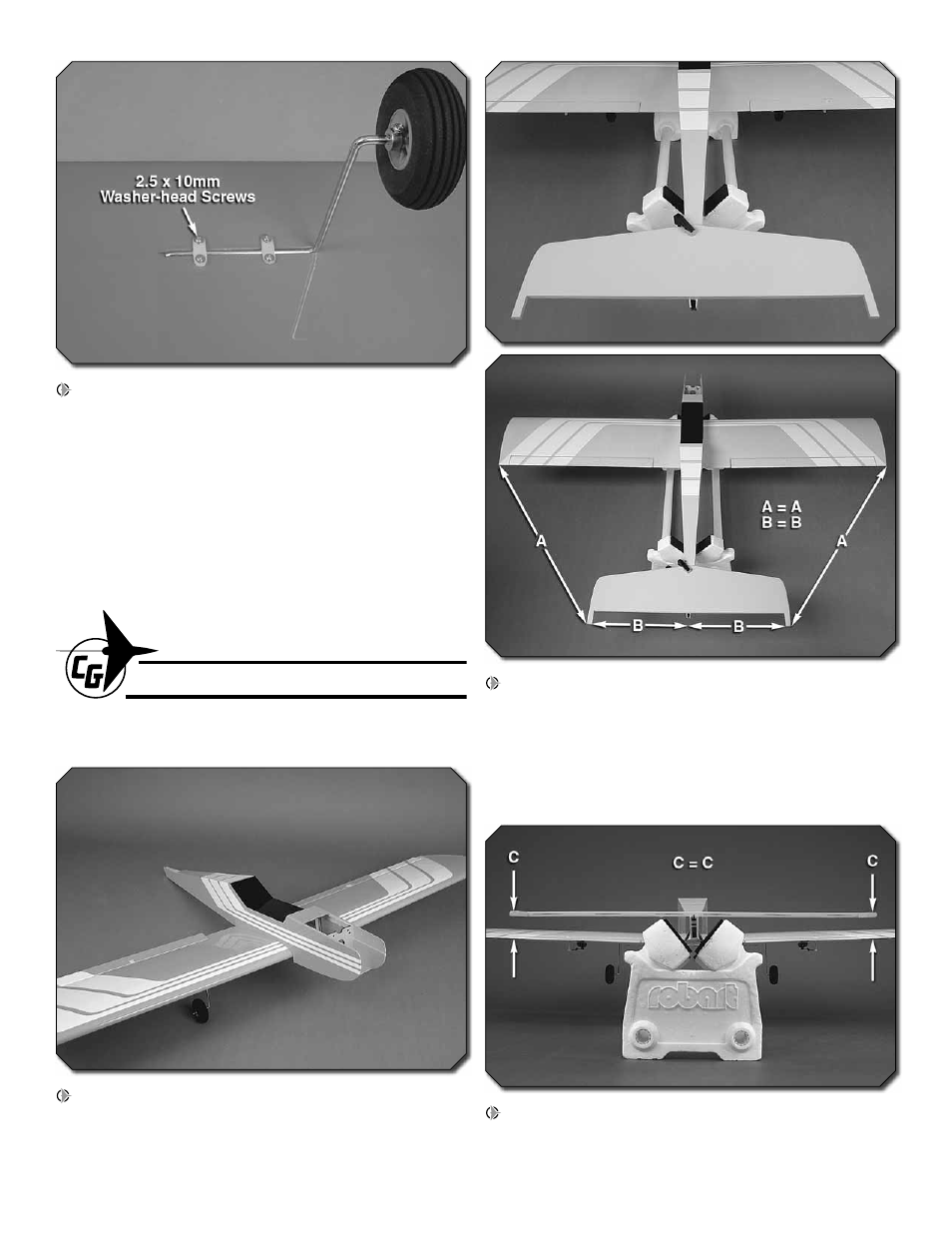
3. Position two landing gear straps evenly spaced apart
over each landing gear and mark the location of the strap
holes onto the wing. Drill holes at your marks using a 1/16"
[1.6mm] bit. Thread a 2.5x10mm self-tapping washer head
screw into each hole and back it out. Apply a drop of thin CA
to each hole to harden the wood. When the glue has dried,
install the straps using eight 2.5x10mm self-tapping washer
head screws.
BUILD THE FUSELAGE
INSTALL THE TAIL SURFACES
1. Temporarily install the wing onto the fuselage using two
4x25mm machine screws and two 4mm fl at washers. The
wing will be used to properly align the horizontal stabilizer
onto the fuse.
2. Place the horizontal stab onto the stab saddle as shown.
Center the stab left and right on the fuse (making a center
mark on the stab is helpful) and make the distance between
wing and stab tips equal on both sides. When satisfi ed, use
a felt-tip pen to trace around the saddle where it meets the
underside of the stab. We used a small clamp to hold the
stab in place while we did this.
3. Stand back 5-6 ft [1.5 - 1.8m] and view the model from
behind. Confi rm that the stab and wing are parallel. If not,
sand the fuselage as necessary until they are parallel.