Carl Goldberg GPMA1960 Gentle Lady Glider ARF User Manual
Page 6
6
7. Fit the fi n post into the slot in the stab. Trace around
the fi n, being sure it is aligned over the fuse center line (a
reference line drawn on the fuselage is helpful to keep the
fi n aligned with the center of the fuselage. Cut the covering
1/16" [1.6mm] inside the lines you drew and use alcohol to
wipe away the lines.
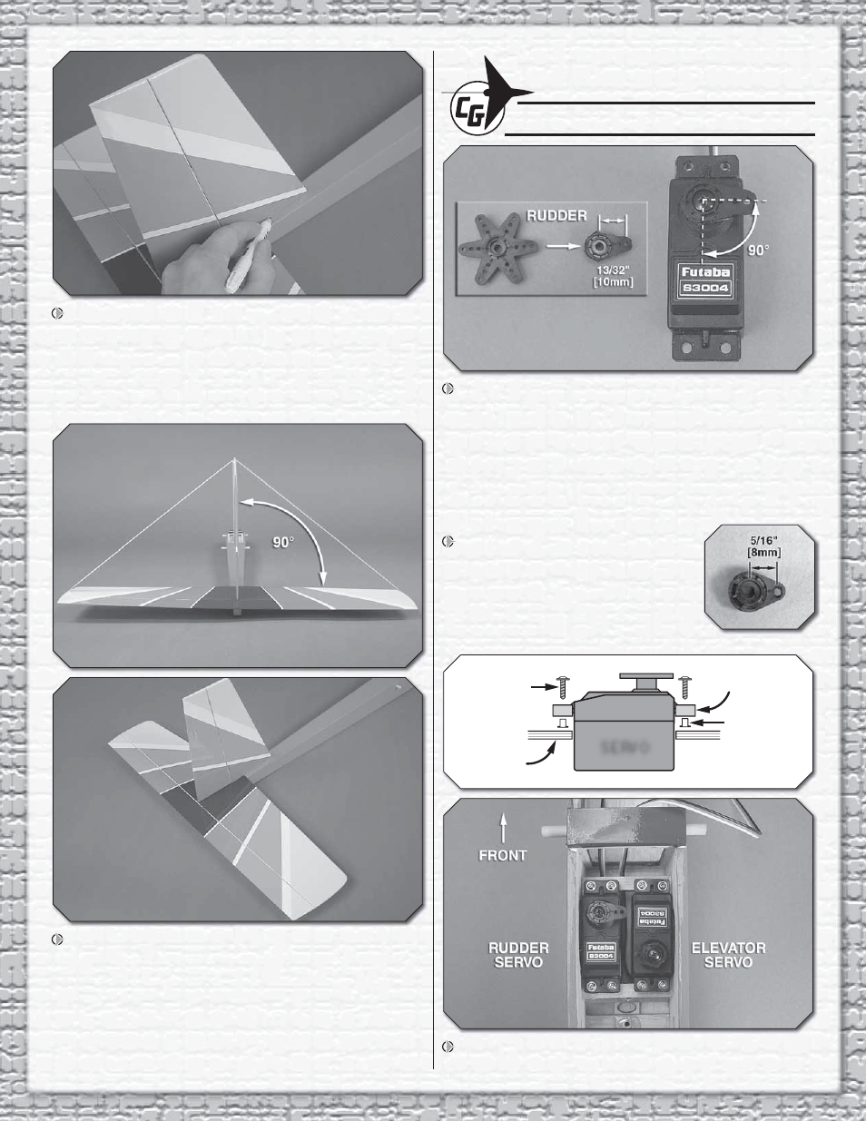
8. Epoxy the fi
n in place. Confi
rm that the fi
n is
perpendicular to the stab. Use tape if necessary to hold the
fi n square to the stab while the epoxy cures.
INSTALL THE SERVOS & PUSHRODS
1. Select a servo arm that offers a hole location of 13/32"
[10mm] from the center. Remove all but one of the arms of
the servo arm. Trim the servo arm beyond the hole that is
13/32" [10mm] from the center. Use a fi le or sandpaper to
round over the corners of the arm. Enlarge the outer hole
with a 5/64" [2mm] drill bit. Center the rudder servo with your
radio system and install the servo arm perpendicular to the
servo case as shown.
2. Prepare the elevator servo arm
in the same manner, but select an arm
with a hole 5/16" [8mm] from the center
and trim the excess length of arm from
beyond the hole. Enlarge the hole with a
5/64" [2mm] drill bit.
SCREW
SERVO
SERVO
TRAY
BRASS
EYELET
GROMMET
3. Position the servos onto the servo rails in the orientation
shown. Drill servo mounting holes using a 1/16" [1.6mm] drill