Installation, Additional options, Wiring information & coding – Avlink EVS-814PF User Manual
Page 2
Installation
1. Connect the AV-Extender Local unit RJ-45 output
connector and EVS-814PF RJ-45 input connector with
the CAT.5 cable.
2. Connect the HD-15 male extension cables between the
monitors and the EVS-814PF video output connector of
the Distribution amplifier.
3. Connect the EVS-814PF audio output connector with the
audio cable from the audio amplifier
4. Connect the power cord and turn on the Distribution
amplifier.
5. EQ and GAIN compensate the loss caused by the length
of the cable, and the VGA output can be connected to a
monitor to view the image quality.
Note:
excessive EQ and GAIN compensation may cause
an incorrect decoding of the EVS-814PF, an abnormal
display, or no display at all.
Additional Options
Select any additional options you may require.
1. It provides perfect skew delay correction, we suggest
when distances over 150M it is needed.
(Item No: SK-101)
-3-
Distances and Resolutions for
CAT.5/5E and CAT.6 cables
50M 2048x1536
100M 1280x1024
180M 1024x768
200M 800x600
CAT.5/5E
300M 640x480
30M 1920x1440
50M 1280x1024
CAT.6
100M 800x600
PS. We suggest to use CAT.5 cable because the
performance is better than others.
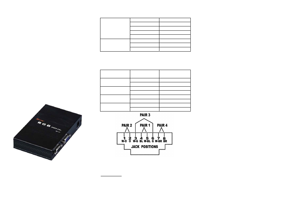
Wiring Information & Coding
Conductor
Identification
RJ45 Pin
Assignment
Color Code for
Conductor
5 White-Blue
Pair 1
4 Blue
1 White-Orange
Pair 2
2 Orange
3 White-Green
Pair 3
6 Green
7 White-Brown
Pair 4
8 Brown
© C&C TECHNIC TAIWAN CO., LTD. All rights reserved.
Trademarks:
All the companies, brand names, and product names
referred to this manual are the trademarks or
registered trademarks belonging to their respective
companies.
-4-