Installation, Operation, Wiring information & coding – Avlink CRM-41A User Manual
Page 2
10. Port 2 LED: This is the PORT 2 LED while in general
mode. This LED blinks when selected.
G LED: While in RGB Skew selection mode, and
while in G selection mode, the LED is lit.
11. Port 3 LED: LED for PORT 3 while in general mode.
LED blinks when selected.
B LED: While in RGB SKEW adjust mode outputting
to B adjust mode, the LED will be lit.
*While in CRM-21/21A, this LED will not light up in
general mode, but will light up in adjust mode.
12. Port 4 LED
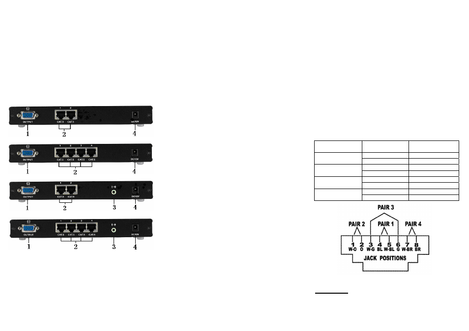
REAR VIEW
CRM-21
CRM-41
CRM-21A
CRM-41A
1. VGA Output
2. RJ-45 Input
3. Audio Output
4. Power Jack
-3-
Installation
1. Connect the VGA-Extender or AV-Extender local unit
RJ-45 output connector and CRM-21/CRM-41 or
CRM-21A/CRM-41A RJ-45 Input connect with CAT.5
cables.
2. Connect the CRM-21/CRM-41 or CRM-21A/CRM-41A
VGA output connector with HD-15 male to male cable
from monitor.
3. Connect the CRM-21A/CRM-41A audio output
connector with audio cable from audio amplifier.
4. EQ and GAIN compensates the loss caused by the
length of the cable, and the VGA output can be
connected to a monitor to view the image quality.
Note: Excessive EQ and GAIN compensation may cause
incorrect decoding, abnormal display, or no display at all.
Operation
A. General Mode:
After turning on the power, the power LED and locked
LED will light up, the Port 1 LED will blink, and the rest
of the LEDs will be off.
When a Port's selection key is selected, the
corresponding LED will blink; the Lock key also can be
used to operate adjust mode, while the remaining keys
are non-functional.
B. Adjust Mode:
In normal mode, after selecting Port 1, 2, 3 or 4, press
the Lock key to enter Port adjustment mode. Once the
adjustment is complete, press the Lock key again to exit
Port adjustment mode. Next, save the port adjustment
data and return to normal mode.
Press the Lock key. All of the LEDs will shut off except
for the Power LED. Enter adjust mode.
Pressing the EQ up/down button will adjust the
definition, while pressing both buttons at once returns
to zero.
Pressing the GAIN up/down button will adjust the
brightness, while pressing both buttons at once returns
to zero.
Press the SELECTOR button to choose R, B or G
SKEW adjustment. The selected R, G or B LED will
light up.
A lit R LED indicates that pressing the SKEW up/down
button will adjust the delay time for R. Pressing both
buttons as once returns to zero.
-4-
When the G LED is on, it indicates that pressing the
SKEW up/down button will adjust the delay time for G.
Pressing both buttons and the same time returns to
zero.
When the B LED is lit, it indicates that the SKEW
up/down button adjusts the delay time for B. Pressing
both buttons at the same time returns to zero.
Press the LOCK key when the adjustment is complete.
The Locked LED will light up. Exist adjustment mode,
return to general mode, and save post-adjustment
data.
Note:
1. Pressing the EQ up/down button increases or decreases
voltage by 33mV, to a maximum of 1V.
2. Pressing the Gain up/down button increases or decreases the
voltage by 33mV, to a maximum of 1V.
3. Pressing the RGB SKEW up/down button increases or
decreases delay time by 2ns, to a maximum delay of 64ns.
Wiring Information & Coding
Conductor
Identification
RJ45 Pin
Assignment
Color Code for
Conductor
5 White-Blue
Pair 1
4 Blue
1 White-Orange
Pair 2
2 Orange
3 White-Green
Pair 3
6 Green
7 White-Brown
Pair 4
8 Brown
© C&C TECHNIC TAIWAN CO., LTD. All rights reserved.
Trademarks:
All the companies, brand names, and product names
referred to this manual are the trademarks or registered
trademarks belonging to their respective companies.
-5-