Installation, Ir receiver cable directions, Ir blaster cable directions – Avlink HDMI-SXW User Manual
Page 2: Additional options, Wiring information & coding, Technical specifications output signal
Installation
1. Turn off the DVD and HDTV.
2. Connect the HDMI extension cable between the DVD
and the “HDMI IN” port of HDMI-SLW or HDMI-ELW.
3. Connect the HDMI extension cable between the HDTV
and the “HDMI OUT” port of HDMI-SRW or HDMI-ERW.
4. Connect the CAT.5 cables between the HDMI-ELW
“LINK” port and the HDMI-SRW or HDMI-ERW “LINK”
port of extender.
5. Connect the power cord and turn on the extender.
6. Turn on the DVD and HDTV.
※When HDMI-ELW is in BYPASS mode the LINK port
should be left unused.
IR Receiver Cable Directions:
Put it into the HDMI-SRW or HDMI-ERW “IR2 IN” port and
place the IR Receiver Cable, so that you can point to it
easily with your IR remote controller.
IR Blaster Cable Directions:
Plug IR blaster cable plug into HDMI-SLW or HDMI-ELW
“IR OUT” port, It sits in front of the DVD receiver’s IR
sensor, which is located on the front-panel.
Additional Options
Select any additional options you may require.
1. IR Receiver Cable
GND
+V
Sig
2. IR Blaster Cable
NC
P+
N-
-3-
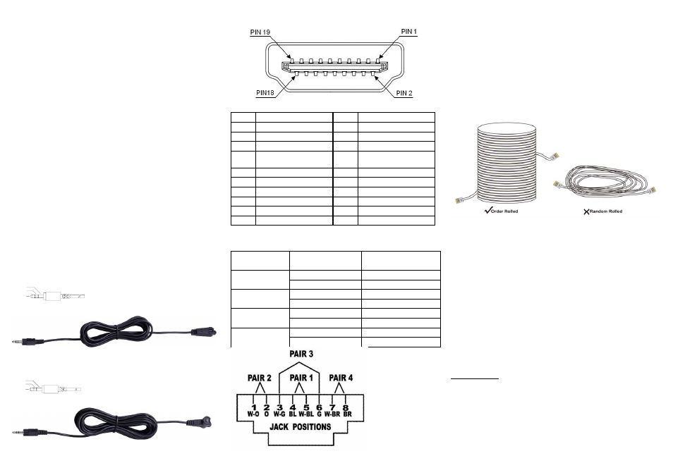
Technical Specifications Output Signal
Pin #
Signal
Pin #
Signal
1
TMDS Data 2+
11
TMDS Clock Shield
2
TMDS Data 2 Shield
12
TMDS Clock -
3
TMDS Data 2-
13
CEC
4
TMDS Data 1+
14
Reserved
(N.C. on device)
5
TMDS Data 1 Shield
15
SCL
6
TMDS Data 1-
16
SDA
7
TMDS Data 0+
17
DDC/CEC Ground
8
TMDS Data 0 Shield
18
+5 Power
9
TMDS Data 0-
19
Hot Plug Detect
10
TMDS Clock+
Wiring Information & Coding
Conductor
Identification
RJ45 Pin
Assignment
Color Code for
Conductor
5 White-Blue
Pair 1
4 Blue
1 White-Orange
Pair 2
2 Orange
3 White-Green
Pair 3
6 Green
7 White-Brown
Pair 4
8 Brown
-4-
Note
However sometimes, especially in demonstrations or in a
lab environment, the cable is rolled randomly in small turns
for convenience. The randomly rolled UTP cable suffers
additional signal impairments (compared to a straight cable)
and therefore the maximal operating reach might be
reduced.
Rolling a CAT5E cable around a 70cm fixed diameter
plastic drum has just a minor effect on the FEXT (Far End
Cross Talk) when compared to a fully stretched
cable.
© C&C TECHNIC TAIWAN CO., LTD. All rights reserved.
Trademarks:
All the companies, brand names, and product names
referred to this manual are the trademarks or registered
trademarks belonging to their respective companies.
-5-