Operation, Chapter 3 – Cabletron Systems 9E138-36b User Manual
Page 21
3-1
Chapter 3
Operation
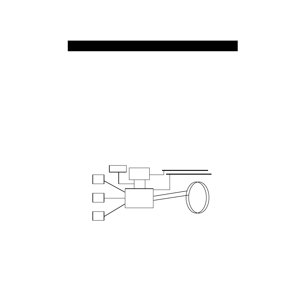
The Ethernet MicroLan Switch Modules provide connectivity between four
interfaces: the three front panel Ethernet and the FDDI rings on the backplane
(FNB-1 or FNB-2).
SmartSwitch 9000 modules connect to either the Internal Network Bus (INB) or
the Flexible Network Bus (FNB) bus. The Ethernet MicroLan Switch Modules
connect to the FNB bus. Figure 3-1 is a block diagram of the modules. The front
panel contains three Ethernet connections that interface to the Repeater Interface
Controllers (RIC). These function as individual repeating networks; each 12 port
group is a separate collision domain. Front panel Ethernet packets are received
via the RIC. Bridging/Routing may occur between these RICs and/or to any
other SmartSwitch 9000 module via the Flexible Network Bus.
Figure 3-1. Ethernet MicroLan Switch Modules Block Diagram
i960 PLUS Core
RIC
RIC
RIC
FNB-1 or
FNB-2
System
Diagnostic
Controller
SMB-10
SMB-1
DC/DC
Converter