Stainless steel junction box mounting and wiring – Kistler-Morse KM LD360s User Manual
Page 20
Mounting Junction Box
1.
See Figure 3-7. Hold the junction box at the desired
mounting location. Mark the four mounting holes.
2.
Mount the junction box with #8-32 socket head cap
screws and flat washers per your application. Tighten the
screws until snug.
Wiring Load Discs to Junction Box
See Figure 3-8. The stainless steel junction box accommodates up to
eight Load Discs, with up to two Load Disc wires at each terminal.
Note that the junction box has no pre-cut holes for conduit or fittings.
Follow this procedure:
1.
Prepare junction box —
a.
Remove the junction box cover.
b.
Remove the terminal board from the junction box.
c.
Carefully lay out the conduiting configuration —
the Load Disc cables connect to the terminals on
the left and the signal processor cable connects
on the right. Several Load Disc cables may enter
the box through the same conduit.
d.
Cut the required fitting holes in the bottom and/or
sides of the junction box.
e.
Install liquid tight fittings.
f.
Seal fittings with Sikaflex™ or electrical grade
sealant.
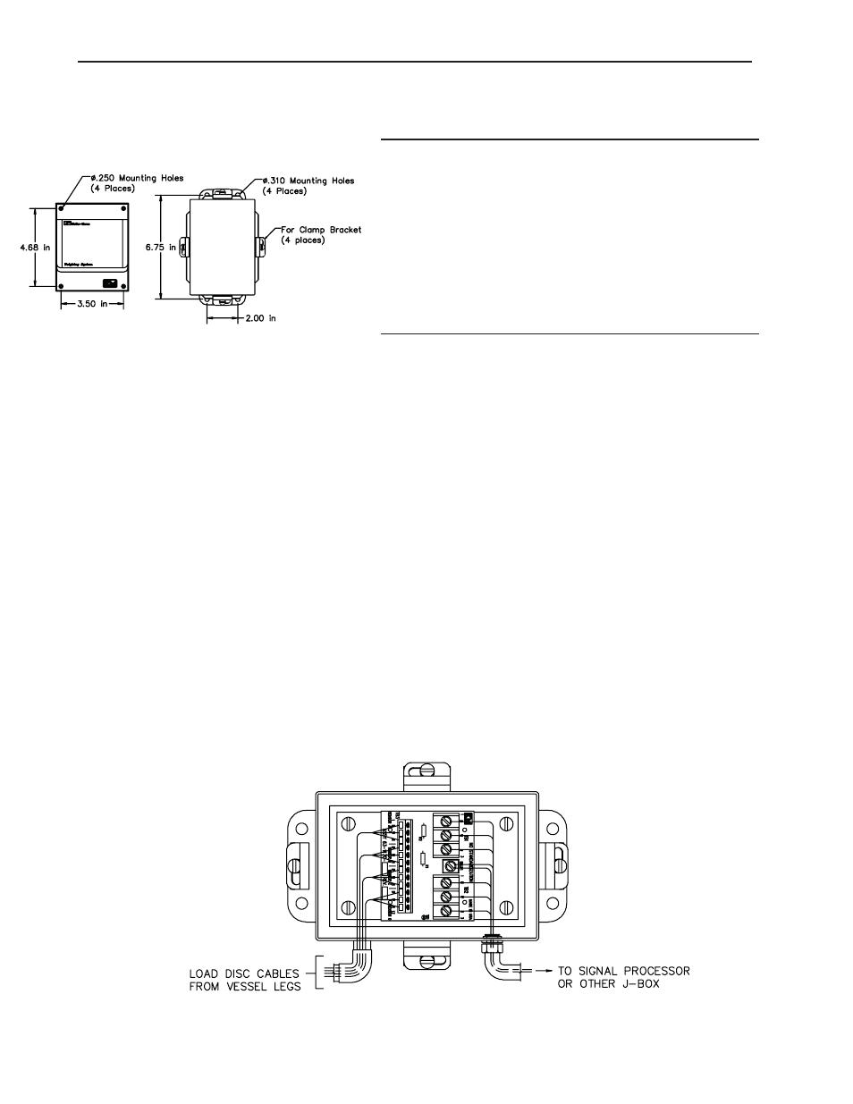
Stainless Steel Junction Box Mounting and Wiring
Figure 3-7: Plastic and
Stainless Steel Junction Box
Mounting
Figure 3-8: Wiring Load Discs to Stainless
Steel Junction Box
Chapter 3: Mounting the Load Disc
3-7