Installation – Inovonics FA575X User Manual
Page 3
FA575X Installation Instructions
Page 3 of 4
Rev. 1.00 F575X_V1.FM 08/24/2000
Installation
Mounting repeaters:
•
Repeaters should be mounted in locations indicated by the system designer.
•
Do NOT mount repeaters on metal surfaces or inside metal enclosures. Do not
mount where sheet metal ductwork, wire mesh screens, etc. might unnecessarily
block transmissions. The FA575 housing has an inside knockout to permit wires
from power sources to be brought into the housing from behind the unit.
•
The repeater unit also has a removable shutter to permit wires to enter the hous-
ing from the side of the unit.
Power Supply:
•
The 14VAC transformer provided by the user requires an unswitched power out-
let.
•
The case of the 14VAC transformer provided by the user should be secured to the
electrical outlet to prevent accidental unplugging.
•
Recommended AC power requirement of repeater: 14VAC (only) at 20VA.
•
Recommended backup power requirement (optional): 12 VDC, 1.2 Ah.
(BAT603) Note that ACC640 Receiver Enclosure or equivalent is needed to
mount the battery and receiver.
•
Recommended wire requirements: 2-conductor 20AWG (or larger) stranded
tinned copper with PVC insulation rated to 300 volts @ 80°. (Belden #8205, for
example.) Maximum recommended wire length between transformer and
repeater: 100 meters (328 feet). Measure voltage at repeater on long wire runs.
(Source: Tech Note #1053)
•
Wire runs should be hidden or protected by conduit.
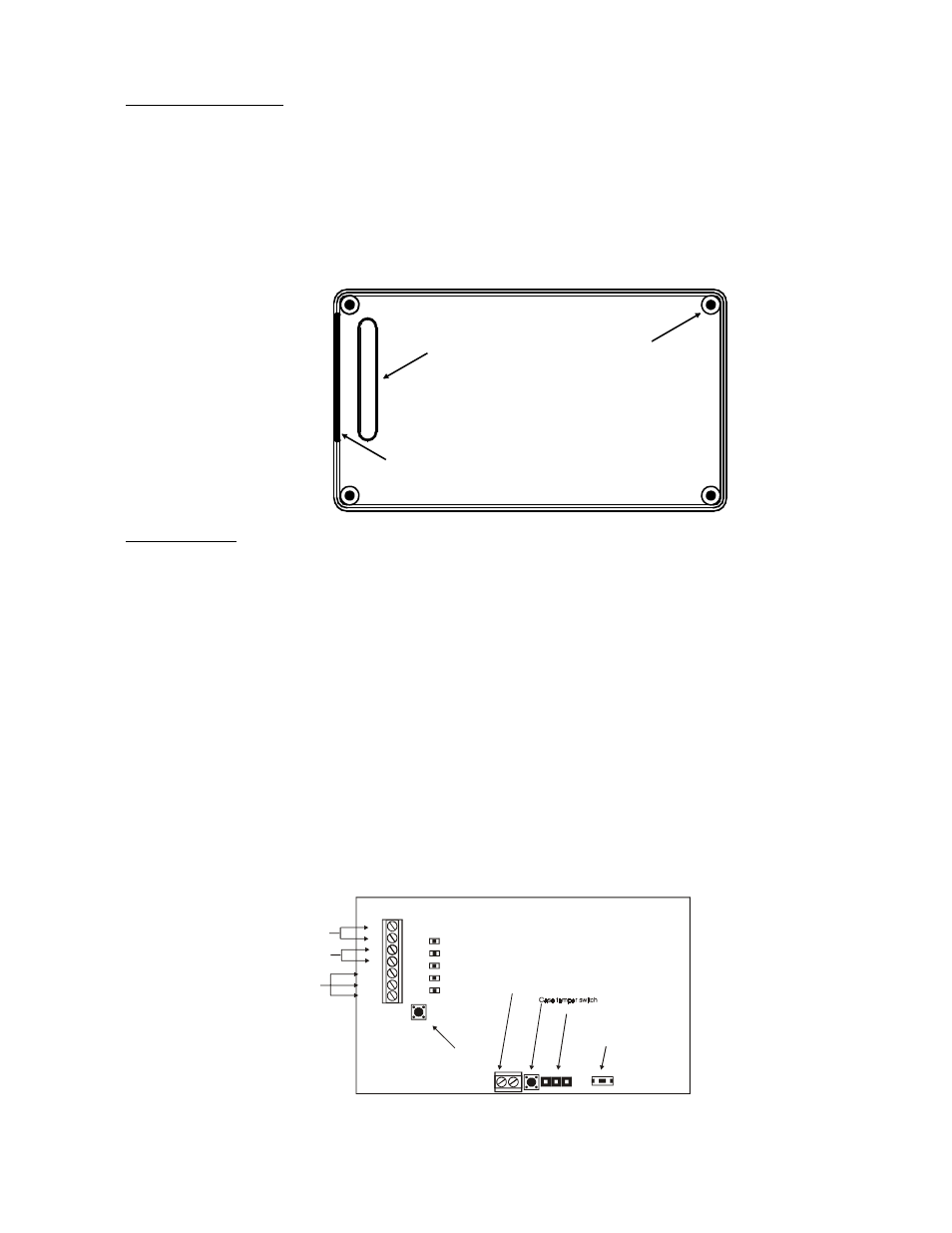
Wiring knockout
Wiring shutter
Mounting holes
(4 places)
AC
BATTERY
TEST
DECODE
TRANSMIT
NOT ACTIVE
AC
AC
B+
B-
OUT
RESET
GND
RESET
AC Transformer
Backup battery
(optional)
Not used
Test Button
Reset Button
Programming header
External terminal (optional use with exterior enclosure)